
Instruction manual


MODEL 2025 TOOL ALCOA FASTENING SYSTEMS
12
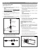
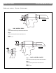
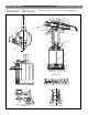
6. Remove Spacer (22) and O-
Ring (68) from spring side of
end cap.
7. From bottle side of end cap,
remove Retaining Ring (66),
Wiper Housing (67), Wiper
Seal (23), Washer (71) and
O-Ring (69).
8. Remove the O-Rings (65)
from the inside of the
Adapter and Tube/Slide
Assembly (70) (Fig 15).
19
22
68
21
69
71
23
67
66
FIG. 6
Head/handle 2025, 2025B, 2025L & 2025LB
(Refer to Figures (7, 8 & 14)
NOTE:
Clean components with mineral spirits, or similar solvent;
inspect for wear/damage and replace as necessary.
Replace all seals of disassembled components. Use O-
rings, QUAD rings and Back-up rings in Service Parts Kit,
P/N 2025KIT or 2025VKIT Smear LUBRIPLATE 130AA or
PARKER-O-LUBE on O-rings, QUAD rings, Back-up rings
and mating parts to ease assembly. Assemble tool taking
care not to damage O-rings, QUAD rings, or Back-up rings.
1. If removed, position Cable Assembly (2) in Trigger (5)
slot and slide Dowel Pin (3) through holes in trigger
and cable assembly. Position assembled trigger in
handle and drive Pin (4) through holes in handle and
trigger (Fig. 14).
2. Screw Nose Adapter (8) into Head (1) and tighten.
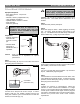
3. Thread POLYSEAL Insertion/removal Tool (121694-
2025) into head.
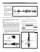
4. Assemble piston (6), Polyseal (18) and retaining ring
(16) (Fig 7). Note Polyseal orient
ation.
5. Assemble front gland (15), O-ring (12), Back-up ring
(11), Polyseal (14) and Gland Cap (10). Note Polyseal
orient
ation.
6. Thread Piston Assembly Tool (123111-2 for 2025,
2025B & 2025V) or (123111-4 for 2025L,2025LB &
2025LV) onto Piston (6). Slide complete Gland
Assembly and Wiper Seal (9) onto Piston (6).
ASSEMBLY INSTRUCTIONS 2025 ALL MODELS
LIP, THIS DIRECTION
16
17
18
6
PISTON ASSEMBLY (BULLET)
123111-2 (for 2025, 2025B & 2025V) OR
123111-4 (for 2025L, 2025LB & 2025LV)
11
12
15
14
10
9
LIP, THIS DIRECTION
FIG. 7
1
8
PRESS
POLYSEAL INSERTION TOOL
121694-2025
SUPPORT
FIG. 8