Constellation® Vision System THE CONSTELLATION CASSETTE The cassette is the interface between the Constellation® console and the surgical handpiece. It is used to regulate BSS® irrigating fluid to the handpiece, aspirate debris from the handpiece, monitor irrigation and aspiration pressure, and deposit the debris in a sealed drainage bag for disposal.
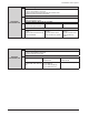
Constellation® Vision System CONSUMABLE PAK CONFIGURATIONS Constellation® Consumables Procedure Paks are available in multiple configurations to meet the user’s needs for each procedure. There are three main types of Consumables Paks: Posterior segment, Anterior segment and Combined Procedure (both Posterior and Anterior), and each type of pak can be customized further to specify items such as gauge specific instruments.
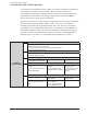
Constellation® Vision System Cassette Building Block: - Posterior Cassette - Premium Administration Tubing Set - Premium Infusion FA/X Tubing Set with Auto Infusion Valve - Auxiliary Aspiration/ Extrusion Tubing Set Vit Building Block (20, 23, or 25 GA): POSTERIOR PROCEDURE PAK - 5000 cpm UltraVit™ Probe with ENGAUGE™ RFID - 2500 cpm UltraVit™ Probe Light Guide Building Block (20, 23, or 25 GA): - 20 Ga STD Illuminator - 20 Ga Wide angle Illuminator - 23 Ga STD Illuminator - 25 Ga STD Illuminator Poste
Constellation® Vision System SECTION THREE OPERATING INSTRUCTIONS INTRODUCTION This section details the recommended setup and operation for the Constellation® Vision System. These procedures may be modified to conform to hospital requirements and practices as you become experienced in using the system. The operational checks however, that are performed at various points in the setup procedure to verify instrument operation, must be performed exactly as indicated.
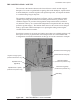
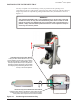
Constellation® Vision System POSTIONING THE INSTRUMENT TRAY The tray is capable of accommodating a variety of positions in the operating room environment: right, left, front and rear of the surgeon as well as the front of the bed. The tray height and position are adjustable by pulling the Instrument Tray Latch Release shown in Figure 3-1. WARNING! The maximum allowable load on the instrument tray is 20 lb (9 kg).
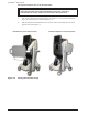
Constellation® Vision System Placing the Instrument Tray in the Stored Position WARNING! Place the instrument tray in the stored position (see Figure 3-2) prior to transportation to avoid a situation that could cause the system to tip. 1 Pull the Horizontal/Vertical Latch Release (see Figure 3-1) and rotate the instrument tray to the vertical position shown in Figure 3-2. 2 Pull the Position Latch Release and move the tray and arm assembly into the stored position shown in Figure 3-2.
Constellation® Vision System INITIAL SYSTEM SETUP 1. Matching the red dot on the footswitch cable connector to the red dot on the footswitch, plug cable into footswitch. Plug the other end of the footswitch cable into the rear panel on the console (match red dots for proper orientation). 2. Attach air hose to connector on rear panel. 3. Plug main power cord into a suitable wall outlet or receptacle.
Constellation® Vision System Constellation® Procedure Pak The Constellation® Procedure Paks are available in three (3) procedural pak configurations: Constellation® Vitrectomy Pak, Constellation® Phaco Pak, and Constellation® Combined Procedure Pak. Each pak contains the sterile single-use supplies necessary to perform one Posterior segment, Anterior segment, or Combined Procedure respectively. The Combined Procedure covers both Anterior and Posterior segment procedures. WARNINGS! 1.
Constellation® Vision System The following instructions are applicable to all three procedure paks unless otherwise specified. For the Combined Procedure Pak setup, follow both Posterior and Anterior Segment Priming and Setup procedures. For additional assistance in the setup of the console, press the Setup button on the touch screen monitor. Procedure Pak and Cassette Setup Procedure 1.
Constellation® Vision System Posterior Segment Setup Procedure 1. Connect the Infusion tubing set (Green) to the corresponding cassette port. If the Auto Fluidic Valve tube set is used, connect both connectors (Green and White). The connectors and cassette ports are color coded and keyed for ease of identification. Insert the connectors into the cassette port and turn clockwise until fully engaged. Scrub Nurse 2. Open the side compartment of the Infusion Cannula tray to gain access to the luer fitting.
Constellation® Vision System Anterior Segment Setup Procedure 1. Connect the Irrigation/Aspiration tubing set (Light Green/Light Blue) to the corresponding port on the cassette. The connectors and cassette ports are color coded and keyed for ease of identification. Insert Scrub Nurse the connectors into the cassette port and turn clockwise until fully engaged. 2. Thread U/S Tip onto U/S handpiece. Tighten firmly using the Tip Holder Wrench. Remove Tip Holder/Wrench and retain for future tip removal.
Constellation® Vision System 8. When in Surgery screen, select I/A mode. Depress footswitch to position 1 to stream irrigation fluid from the irrigation port and activate reflux function to stream irrigation fluid from the I/A tip’s aspiration port. Observe the stream of irrigating fluid from the irrigation and aspirations ports. If the stream of irrigation fluid is weak or absent, good fluidics response will be jeopardized. Scrub Nurse CAUTION Use of this product may require surgical settings adjustments.
Constellation® Vision System Auto Gas Filler Setup Procedure WARNING! The Constellation® Auto Gas Filler kit is intended for one procedure only. Reuse, improper usage or assembly could result in a potential hazardous condition for the patient (Accreditation Manual for Hospitals, 1982). Alcon assumes no responsibility for complications that may arise as a result of the reuse or improper usage of any part of the kit. 1.
Constellation® Vision System Fragmentation Setup Procedure 1. Scan the bar code on the Constellation® Fragmentation Kit with the Bar Code Scanner in the back of the Constellation® console. 2. Open the pouch and aseptically transfer the sealed plastic tray to the sterile field. The plastic tray that contains the components is considered sterile. Circulator or Non-sterile Scrub Nurse Circulator 3. Peel the Tyvek lid from the plastic tray and remove the contents from the tray.
Constellation® Vision System Viscous Fluid Control Setup Procedure Syringe Adapter Connection WARNINGS! • Do not use if a stream of air bubbles is observed passing through the fluid • Do not use VFC Kit with fluid viscosity greater than 5000 centistoke 1. Scan the bar code on the VFC Kit with the Bar Code Scanner in the back of the Constellation® console. Select VFC in the Accessories panel. Circulator or Non-sterile Scrub Nurse 2.
Constellation® Vision System 4. Connect the syringe barrel to the syringe adapter by pushing down until it bottoms out and rotate the barrel 90°. Ensure that the flanges on the syringe barrel are entirely engaged with the adapter. Scrub Nurse 5. Keeping the Cannula cover on, attach the desired VFC cannula to the syringe. There is both a 20 Ga and 23 Ga Cannula provided with the kit. Scrub Nurse 6. On the VFC screen, set the appropriate vacuum level for the procedure and the device is ready for use.
Constellation® Vision System Extrusion Setup Procedure The extrusion handpiece connects to the suction/aspiration line from the cassette. 1. Present a sterilized extrusion handpiece to Scrub Nurse. 2. For Combined procedure cassettes: Connect the handpiece to the aspiration line (light blue) of the irrigation/aspiration tubing set. The irrigation line (light green) is not used. Use the white male/male luer to adapt the extrusion handpiece to the blue connector of the aspiration line.
Constellation® Vision System Pneumatic Handpiece Setup Procedure The Constellation® Pneumatic Scissors and Forceps Handpieces are designed to be used with the Alcon Constellation® System and any reusable or disposable Grieshaber Microinstrument Tips with Quick Lock Connector. It is provided sterile and is intended for single use. The handpiece can be operated in Multicut (Scissors) or in Proportional mode. The mode of operation must be selected according to the type of tip and the surgical application.
Constellation® Vision System THIS PAGE INTENIONALLY BLANK 3.
Constellation® Vision System SECTION FOUR CARE AND MAINTENANCE INTRODUCTION This section of the manual is designed to inform the operator of basic care and maintenance of the instrument. If a problem occurs on the instrument, call the Alcon Technical Services Department and give details of the breakdown circumstances and effects. From these elements, a specialized technician will evaluate the problem and determine the maintenance requirements.
Constellation® Vision System UPON COMPLETION OF THE PROCEDURE STEP ONE: Clean handpieces, probes, cables, forceps, etc., as instructed in DFU's supplied with each accessory. STEP TWO: Remove irrigation bottle from hanger and set aside. Remove spike from irrigation bottle and discard tubing. STEP THREE: Eject cassette and discard. STEP FOUR: Flip the irrigation bottle holder to its storage position. STEP FIVE: Press Standby power switch located at top of rear panel to remove operating power from the system.
Constellation® Vision System STERILIZATION INSTRUCTIONS Please consult the accompanying Directions For Use (DFU) for cleaning and sterilization instructions for Alcon approved reusable accessories. The DFU will provide the recommended time and temperature guidelines for steam autoclave cycles performed by Alcon, Inc. The sterility assurance level achieved with these parameters must be validated by each surgical facility.
Constellation® Vision System Reusable Handpiece and Accessories Cleaning and Sterilization Instruction The following cleaning instructions provide a method for effectively cleaning the reusable U/S and handpieces and accessories. Due to the potential for Toxic Anterior Segment Syndrome (TASS), Alcon does not recommend the use of enzymatic cleaners and detergents.
Constellation® Vision System 3 Automated Washer Cleaning Procedure In the event use of an automated process is required, perform all of the following steps to process the handpiece. NOTES: a) Due to the potential for the accumulation of particulate and bioburden residues in the washer water reservoirs, it is the surgical facility’s responsibility to properly maintain the equipment and their associated filters to ensure the introduction of contaminant-free solutions into the handpieces.
Constellation® Vision System 3.5 Using the Auto Wash Kit, secure the handpiece to the wire mesh basket using the small gauge wire and connect the handpiece with the “Y” adapter assembly as shown. Figure 4-1. 3.6 Place wire basket with handpiece in multi-purpose injector rack and connect the “Y” adapter assembly to the 4 mm diameter injector nozzle as shown. Figure 4-2. 3.7 Auto Wash: "Y" Adapter Connected to Injector Nozzel Plug off any unused injector nozzles with silicone tubing. Figure 4-3. 4.
Constellation® Vision System 3.8 Start the wash program. When the wash program is completed, replace the processed handpiece and cable in the sterilization tray to prevent damage to connector and handpiece during storage and autoclaving. 4 Sterilize the handpiece using a steam sterilization cycle. The sterilization temperatures and settings provided in Table 1 below have been validated by Alcon Laboratories, Inc.
Constellation® Vision System Disposal of Xenon Lamps WARNING! The bulb of the xenon lamp is under constant high pressure. There is a risk it may burst with explosive force if knocked or damaged. Protective measures: - Keep the lamp in its protective sleeve at all times during installation - If you are handling the lamp without its protective sleeve, always wear safety goggles, a face mask, gauntlets with wrist protectors and a breast protector.
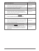
Constellation® Vision System SECTION FIVE TROUBLESHOOTING Table 5-1 is a general troubleshooting guide that addresses symptoms/observations and what the operator can do to try and solve the observed problem. Figure 5-5 and Table 5-2 are presented as aids to rapid location of failed or malfunctioning parts or components in the Constellation® Vision System; they are not meant to replace standard troubleshooting methods.
Constellation® Vision System System Error Messages System Error Messages are displayed in a dialog box as shown in Figure 5-2 System Errors require a partial system shutdown. When an error is detected, the following actions occur. • Surgical modes related to the error are disabled. • A System Error dialog box is displayed. If the error does not affect the current active modes, they will remain activated, but the System Error dialog will still be displayed.
Constellation® Vision System Advisory Messages Advisory Messages are displayed in a dialog box as shown in Figure 5-3. Advisory Messages indicate a minor failure in the system, typically a situation that can be corrected by the user. When an advisory is detected, the following actions occur: • Surgical modes relating to the advisory are not available. • An Advisory Message popup window is displayed.
Constellation® Vision System Problem Encountered Figure 5-5 5.4 No message is displayed, but unable to setup and operate as described in this operator's manual and other applicable labeling. Follow the Problem Conditions table in this section of the operator’s manual. If unable to fix the problem, or if the problem is not described in the troubleshooting table, contact Alcon Technical Support or your local Alcon representative. Unit displays an Advisory number and message.
Constellation® Vision System SECTION SIX ACCESSORIES AND PARTS In this section of the Constellation® Vision System Operator's Manual is a list of Alcon-approved accessories and replacement items. Use of non-approved accessories cannot be permitted. Please contact the Alcon Sales Department for in-service information prior to initial use of handpieces, accessories, or paks. For additional information, please contact the Alcon Sales Department.
Constellation® Vision System Table 6-1. Constellation® Vision System Accessories Description Current Part/Catalog Number Description Current Part/Catalog Number 25 GA Wide angle with RFID 8065751185 30° Round, 0.9 mm Tapered ABS® Tip 8065750278 Light probe, Bare End 8065750998 8065750279 Light probe, Ryan Pik 8065751000 45° Round, 0.9 mm Tapered ABS® Tip Light probe, End Irrig 8065751001 8065750280 Light probe, Mem Pik 8065751002 30° Kelman®, 0.
Constellation® Vision System Table 6-1. Constellation® Vision System Accessories Description Current Part/Catalog Number I/A Tip 0.3 mm Bent & Sand Blast 356-1020 Silicone I/A Tip, Straight Silicone I/A Tip, Bent Straight Tip, .3 mm 8065750439 45° Bent Tip, .3 mm 8065750439 90° Bent Tip, .
Constellation® Vision System THIS PAGE INTENTIONALLY BLANK 6.