
User`s manual


Alcorn McBride Binloop User’s Manual Page 77
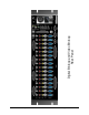
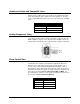
Connectors
This table lists all connectors on the Binloop Card Cage and their related
function. The connectors are all located on the rear of the Binloop. If the
connector is a single signal, then the signal is listed. If the connector
contains multiple signals, the connector's pins are identified in further
tables.
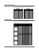
Connector Summary
Connector Type Function
Video RCA/F (Yellow) x 16 Composite Video Outputs
Component HD-15 x 16 Component Video outputs (YUV/RGB)
*SDI BNC Female x 16 SMPTE 259M SDI Digital Video Outputs
Unbalanced Audio RCA/F (Red-Wht) x 32 Unbalanced Stereo Audio Outputs (Right-Left)
Show Control DB-9/M RS-232 to Control System
Programmer Port DB-9/M RS-232 to Programmer
VSYNC BNC Female Blackburst Video Sync Input
SMPTE DB9/F SMPTE Input/Output
MIDI In DIN5/F MIDI In
MIDI Out DIN5/F MIDI Out
Parallel Control DB37/F Control and I/O
Balanced Outputs
1-4, 5-8, 9-12, 13-16
DB25/F x 4 Balanced Stereo Audio Outputs
AES/EBU & S/PDIF I/O DB37/F x 2 AES/EBU or S/PDIF Digital Audio I/O
**CobraNet RJ-45 CobraNet Audio Network
Ethernet RJ-45 Ethernet Control
* Although the SDI connectors are always present of the back of the
Binloop, they are not active unless the Binloop’s reproducers are
equipped with the optional SDI upgrade.
** The CobraNet connector is only available if the optional CobraNet
Card is installed in the Binloop.