DMX OverRide User’s Guide ™
(This page intentionally left blank) ii
Every effort has been made to assure the accuracy of the information contained in this manual, and the reliability of the Alcorn McBride DMX OverRide™ hardware and software. Errors can sometimes go undetected, however. If you find one, please bring it to our attention so that we can correct it for others. Alcorn McBride welcomes comments and suggestions on the content and layout of its documentation. Applications described herein are for illustrative purposes only. Alcorn McBride Inc.
Table of Contents Welcome!............................................................................................................................ 1 Getting Started .................................................................................................................... 1 Battery Connection ......................................................................................................... 1 Rear Panel ......................................................................................
Welcome! Thank you for purchasing the Alcorn McBride DMX OverRide™. The DMX OverRide allows you to take manual control of your DMX network. In normal operation it simply feeds through your DMX stream. But activate any of its remote inputs or pushbuttons, and it automatically overrides the streams with any of three pre-programmed looks. That makes the DMX OverRide ideal for fire alarm lights, work-light presets, manual Blackouts, and much more.
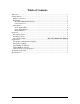
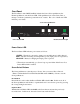
Rear Panel The rear panel of the DMX OverRide includes the DMX Input and Output connectors, the configuration DIP switches, and the Power connector. Power Connector DMX Input Configuration Configuration DMX In DMX Out Remote Input Connections Rear-Panel DIP Switch Settings If possible, it’s a good thing to make sure the rear-panel DIP switches are set the way you want before installing into the rack. The DMX OverRide rear panel contains two banks of DIP switches.
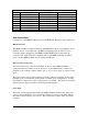
Position 1 2 3 4 5 6 7 8 Right DIP Switch Bank - Input Configuration Input OFF (UP) ON (DOWN) SCENE1 Voltage Input Contact Closure SCENE2 Voltage Input Contact Closure SCENE3 Voltage Input Contact Closure RESUME Voltage Input Contact Closure SCENE1 Normally Closed Normally Open SCENE2 Normally Closed Normally Open SCENE3 Normally Closed Normally Open RESUME Normally Closed Normally Open Unit Connections Connections to the DMX OverRide consist of the DMX I/O, Remote Control, and Power.
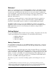
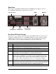
Front Panel The Front Panel of the DMX OverRide includes the Scene Select pushbuttons, the Resume pushbutton, and the Power LED. Each pushbutton also turns Green, Red, or Orange to indicate a particular operational mode or status. The color of the Power LED indicates power status. Scene Selection Buttons Power Status LED Resume/Pass-Through Power Status LED The Power Status LED indicates power status as follows: GREEN – The unit is connected to input power and the battery is fully charged.
Resume Button Pressing the Resume Button will always cause the DMX OverRide to pass DMX data from the input to the output. The button’s multi-color LED indicates the following: GREEN – Resume Mode is active and DMX is actively detected on the input and being passed to the output. ORANGE – DMX is not detected on the input. If the Dropout Enable mode is activated with the rear-panel DIP switch, Scene 1 will activate and the corresponding Scene 1 button will be Green.
Resume Code Feature For applications where you would like your lighting console (or lighting programmer) to resume the lighting without being in front of the DMX OverRide, you can use the Resume Code feature. To do so, the first step is to verify that DIP switch number 6 is OFF.
Applications Here are some ideas of how the DMX OverRide can be used in your installation. Worklights or Maintenance Lighting Many times the person who’s in charge of running the lighting console isn’t around when it comes time to clean the place, or do some work on the theatre. Set up a Work Light preset where the house lights and other general lighting are activated by recording this preset to Scene 2 or 3.
Troubleshooting Guide Troubleshooting Guide Symptom 1) No Front Panel display or LEDs Cause(s) a) Input power not connected. Solution(s) a) Check Power connections b) Replace or Connect Battery b) Battery Dead or disconnected 2) Previous scene not restored after power is cycled 3) Resume button keeps flashing orange. a) Scene selected by rear inputs that are not in the proper position.