Installationsanvisning – Comfort 2923 Installation instructions – Comfort 2923 Montageanleitung – Comfort 2923
1 4 min 90 C 215 A 15 A A 66 132 F F F D 3 780 80 F 1710 min 1850 50 120 75 B 2 Ø58 E B 155 300 G C min 25 5 A A B B 450 440 575 C B 132 105 6 A 400 7 B A B C B 145 D A F C max 500 D 66 Ø 125 Ø 82 E F H I J 9 G 8 A A B B C D 2 E C F D E G
11 10 14 B + - C 42 1 D A E 4 1 5 2 A 6 3 B 12 G A B A B 15 C A D E F D D B 13 C 20 D E 0 20 min 150 40 0 10 3
SE Kapitel Sida 1. Teknisk data 4 2. Montering av värmepannan 4 2:1 Montering av värmepanna inbyggd i skåp 4 2:2 Montering av skorsten 5 2:3 Gasolinstallation 5 2:4 Montering av rumstermostat 5 2:5 Elinstallation 5 3. Montering av värmesystemet 6 3:1 Anslutning till värmesystemet 6 3:2 Fyllning av värmesystemet 6 4. Anslutning av varmvattenberedare 7 5. Installationskontroll 7 Läs noggrant igenom denna installationanvisning innan värmepannan monteras.
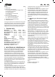
SE DK NO Fig 2 A. B. C. D. E. F. G. Hål för fastskruvning Friskluft Skydd för avgasröret Övre frontplåt Nedre frontplåt Förvärmd friskluft Bärhandtag Fig 3 A. Insugningsrör B. Golv C. Finmaskigt nät Fig 4 avstånd med klammer som ej nöter på röret. Om rörledningen går igenom väggar, golv eller dylikt skall den nötningsskyddas med skyddshylsa av slang eller liknande. Rörledningen skall också vara skyddad mot överslag från elledningar.
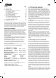
SE DK NO Anslutningen skall ske till ett 12 volts bilbatteri eller speciell batterieliminator. Inkopplingen skall ske enligt fig 10. kran för avtappning av systemet monteras på ledningens lägsta punkt (fig 12 F). 230 VOLT (gäller endast elpatron) Fig 11 Elpatronen skall alltid anslutas till ett 230 volts jordat uttag. Fast installation av vägguttag till 230 volt, skall utföras av behörig person enligt gällande föreskrifter. 12 volts styrkretsen från värmepanna till elpatron är inkopplat från fabrik.
SE DK NO 4. Anslutning av varmvattenberedare (Gäller endast om typ 2959 är monterad) För att varmvattenberedaren skall fungera måste den anslutas till färskvattensystemet. Från beredaren dras sedan slangen med varmvatten vidare till t.ex. dusch, termostatblandare eller diskbänk. På varmvatten beredaren används nipplar med 1/4"R gängor. Gängtape eller dyligt bör sättas i gängorna för att undvika läckage. Färskvattenanslutningarna är placerade på baksidan av beredaren.
GB Chapter Page 1. Technical data 8 2. Fitting the boiler 8 2:1 Mounting a boiler in a cupboard 8 2:2 Fitting the chimney 9 2:3 LPG Installation 9 2:4 Fitting the room thermostat 10 2:5 Electrical installation 10 3. Fitting the heating system 10 3:1 Connection to the heating system 10 3:2 Filling the heating system 10 4. Connection to hot water heater 11 5. Installation inspection 11 Read through these installation instructions carefully before fitting the boiler.
GB end of the hose to make it pointed. Feed the hose out through the ventilation drum and the floor. Attach the ventilation drum to the floor and the boiler by screws. If the boiler is to be mounted in a wardrobe, for example, a dividing wall should be mounted so that flammable material cannot come into contact with any warm parts.
GB 2:4 Fitting the room thermostat The room thermostat should be placed at least 1 metre above the floor, but not too close to the ceiling. It should not be placed on an outer wall, beside the boiler, cooker, fridge or flue. The room thermostat starts and stops the circulation pump according to the heat requirement. 2:5 Electrical installation 12 volts The electrical connection is made at the top of the boiler, where a six-pole terminal block is fitted.
GB growth of bacteria in the system. Filling is carried out through the expansion tank, either manually or with the aid of Alde’s filling pump. This pump both fills and bleeds the system. If the system is filled manually, slowly pour the liquid until the level is approximately 1 cm over the MIN-line in the tank. Bleed the system. Refill if the level has fallen during bleeding. A newly filled heating system should be bled at regular intervals during the first few days of operation. 4.
DE Kapitel Seite 1. Technische Daten 12 2. Installation des Kessels 12 2:1 Montage eines Kessels, der in einem Schrank eingebaut ist 12 2:2 Installation des Schornsteins 13 2:3 Flüssiggasinstallation 13 2:4 Anbringung des Raumthermostates 13 2:5 Elektroinstallation 13 3. Installation der Heizanlage 14 3:1 Anschluß an das Heizsystem 14 3:2 Auffüllung des Heizsystems 14 4. Anschluß des Heißwasserbereiters 15 5.
DE Trennwand Löcher zu bohren (2923, Abb. 4 und 2928, Abb. 3), so dass die Entlüftungsschraube des Warm wasserbereiters, der Abzapfhahn sowie der Rückstellknopf für den Überhitzungsschutz auf der Elektropatrone zugänglich sind. Abb. 1 A. Loch für Frischluftkasten B. Loch für Ansaugrohr Abb. 2 A. B. C. D. E. F. G. Loch zur Befestigung des Kessels Frischluftzufuhr Schutznetz oder -blech für das Abluftrohr Obere Blechverkleidung Untere Blechverkleidung Vorgewärmte Frischluft Tragegriff Abb. 3 A.
DE 3. Installation der Heizanlage Um die bestmögliche Leistung aus dem Heizsystem herauszuholen, sollten die Heizkörper an den Außen wänden und unter den Fenstern angebracht werden (siehe Abb. 12). Damit Luftzirkulation (Abb. 11) und Wärmeabgabe richtig funktionieren, sollte die Luft frei zwischen den Bettenböden und dem Fußboden sowie zwischen Rückenlehnen und Außenwänden zirkulieren können.
DE 4. AnschluSS des HeiSSwasserbereiters (Falls vorhanden) Die ordnungsgemäße Funktion des Heißwasserbereiters setzt einen Anschluß an die Trinkwasserversorgung voraus. Aus dem Speicher wird sodann der Schlauch mit dem Heißwasser weiter zur Dusche, Thermostatmischbatterie oder Spüle verlegt. Am Heißwasserbereiter sind Nippel mit einem Gewinde von 1/4"R zu verwenden, das mit Gewindeabdichtband oder ähnlichem Material gegen Undichtigkeiten abzusichern ist.
V-2923 02 Rev 1163, 200 ex, 2010-07-06 Alde International Systems AB Wrangels allé 90 • Box 11066 • 291 11 Färlöv • Kristianstad • Sweden Tel +46 (0)44 712 70 • Fax +46 (0)44 718 48 • www.alde.se • e-mail: info@alde.