GB Service Manual – Compact 3000, 92X 93X 94X
FOREWORD This service handbook is intended to assist with servicing and fault-finding in caravans and motor caravans equipped with the Alde Compact 3000 92x-94x. The handbook may also be of assistance in ordering spare parts. It also provides general information on how Alde central heating systems are designed, and how they operate. When servicing components designed for LPG and 230 volts, national safety regulations must be adhered to.
CONTENTS Page Chap 3 4 5 5 6 6 7 7 7 8 8 9 9 9 9 9 10 10 10 1:0 Page Chap 1:0 1:1 2:0 2:1 3:0 3:1 About the Alde central heating system Care of the heating system About the Compact 3000 Technical data Fault-finding The electrical heating cartridge does not work 3:2 The LPG boiler do not start 3:2:1 The LPG boiler shuts down on start-up 3:2:2 No ignition spark 3:2:3 Ignition spark is generated but the boiler does not start 3:3 The LPG boiler starts but goes out after approx.
1:1 Adding liquid: MAINTAINING THE HEATING SYSTEM Check the heating system’s fluid level regularly in the expansion vessel. The level should be approximately 10 mm above the ”min” mark when the system is cold. The heating system should be filled with a mixture of water and glycol. For preference, use high quality pre-mixed glycol (with inhibitor) intended for use in aluminium heating systems. If using concentrated glycol, the mixture should consist of 60% water and 40% glycol.
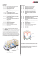
2:0 ABOUT THE COMPACT 3000 How the boiler works. The set-up of the boiler When the room thermostat calls for heat, i.e. the temperature in the vehicle is lower than the set room temperature, the circulation pump starts. The liquid in the heating system then starts circulating, and cold liquid enters the boiler. The boiler’s operating thermostat senses that the temperature of the liquid is too low. A signal is sent to switch on the fan.
BE AWARE OF THE RISKS OF 230 V DURING ALL SERVICE WORK 3:0 FAULTFINDING Fig 1. 3:1 THE ELECTRICAL HEATING CARTRIDGE DOES NOT WORK Cause: - Check that the changeover switches on the control panel are in the correct positions (see operating instruction for boiler). - The 12 V fuse has blown. - No or low voltage to the boiler. (< 12 V). - 230 volt not connected. - The overheating protection device has been triggered. - The thermostat is broken/damaged - Damaged printed circuit board.
3:2 THE LPG BOILER DOES NOT START When the overheating protection device has been reset, there should be a 12-volt input on one flat-pin connector, and a 12-volt output on the other (see fig. 2 A), otherwise it is defective and must be replaced. The overheating protection is broken if there is 12 volt on only one cable. NB! If the overheating protection device has tripped, it cannot be reset until the boiler has cooled by 10-20°C. Before the boiler is restarted, check that it has been bled thoroughly.
- Remove the nozzle and blow the nozzle and gas pipe clean. - Check the wiring contact points again. - Check that the exhaust cowl and the intake/exhaust hoses are free from objects that may obstruct the air supply. - Check that there is voltage (12 V) on flat-pin terminal 12 (grey cable, low temperature) and terminal 22 (blue cable, high temperature) see fig. 2. If there is no voltage on terminals 12 and 22, but there is voltage on terminal 11 (red cable), the operating thermostat must be replaced.
3:4 THE LPG BOILER STARTS AND SWITCHES OFF AT SHORT INTERVALS Cause: - - Check that the flue is free from objects that may obstruct the air circulation. - Check that the gas pressure to the boiler is correct (28-50 mbar). - Where the ignition is unstable, remove the soft start valve and test-start the boiler. The start should now be stable, but with a more violent ignition than normal. Replace with a new soft start valve or clean the old one and carry out another test-start.
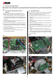
4:0 REPLACING COMPONENTS Always switch off 12 V DC and 230 V ~ power supply and turn the main gas cock to "off" position before starting any servicing. The seals (marked in red) must NOT be broken unless special permission has been obtained from Alde. 4:1 REPLACING THE PRINTED CIRCUIT 4:2 REPLACING FAN BOARD 1. Remove the cover and the service panel from the boiler. 1. Remove the cover and service panel on the boiler. 2. Detach the blue (N) (fig. 7 A) and brown (R) (fig.
4:3 REPLACING THE BURNER NB! Items 9-12 shall be ignored on boilers with manufacturing no 3000 9xx B and on boilers where burner 3000 516 is installed. 9. Adjust the pressure switch screw 1/2 turn clockwise 10.Remove the as in item 4.2 and the under the inlet plate under impeller by removing the two screws. 11.Install the new inlet plate, and then put back the old one, two screws. 12.Remount the fan in reverse order. NB! Take care that the impeller does not get damaged during fitting.
4:6 REPLACING THE SOLENOID VALVE 3. Using two spanners, slacken the nuts on the incoming gas pipe (fig. 15 A) and the gas pipe to the burner (fig. 15 B), and remove the rubber cap from the soft start valve (fig. 14 D). 4. Detach the pressure switch hoses to and remove the insulation next to the burner housing. 5. Unscrew the two plate screws which fasten the gas valve angle bracket to the burner housing. 6.
4:7:1 REPLACING THE 1 KW HEATING CARTRIDGE 1. 2. 3. 4. 5. 6. NB! Check that the rubber plug is fully inserted and push the lower edge of the heating cartridge while tightening the nut. Tighten the nut to 4 Nm. 11. Connect the cables according to fig. 20, (A=brown, B=blue, C=yellow/green). Fit the cover and end plate. Add glycol mixture. Bleed and test-run the boiler. Fig 17. Fig 19. Fig 18. Fig 20. Switch off 230 V power supply Drain the glycol mixture from the heating system.
4:7:2 1. 2. 3. 4. 5. 6. 7. 8. 9. REPLACING THE 2 KW HEATING CARTRIDGE Switch off 230 V power supply Drain the glycol mixture from the heating system. Remove the cover and end plate. Remove the burner together with the solenoid valve (fig. 21). Do not slacken the gas pipe, this is in order to avoid having to check sealing. Remove the cables from the heating cartridge.
4:8 REPLACING THE OPERATING THERMOSTAT 4:9 REPLACING THE OVERHEATING PROTECTION DEVICE 1. Remove the cover on the boiler. 2. Remove the locking clip (fig. 24 A). Remove the split pin (fig. 24 B) on the immersion pipe. Remove the overheating protection device sensor first (fig. 25), and then the operating thermostat sensor (fig. 26 A). 3. Unscrew the two screws which secure the operating thermostat (fig. 27 A) to the fastening plate, and remove the cables from the flat-pin connections. 4.
4:10 REPLACING THE PRESSURE SWITCH 5:0 1. Remove the cover and end-plate from the boiler. 2. Detach the blue, white and red cables on the pressure switch. 3. Push back the metal securing plate and pull out the pressure switch (fig. 28 A). 4. Detach the rubber hoses (fig. 28 B) from the pressure switch (do not pull the hoses, unscrew them). 5. Refit the hoses to the new pressure switch before pushing it into place. 6.
6:0 WIRING DIAGRAM WITH CONTROL PANEL 3000 266 17
6:1 WIRING DIAGRAM WITH CONTROL PANEL 3000 380 18
6:2 WIRING DIAGRAM WITH CONTROL PANEL 3000 465 6:3 WIRING DIAGRAM WITH CONTROL PANEL 3000 465 (WITH AUXILIARY FUNCTIONS) 19
6:4 WIRING DIAGRAM WITH CONTROL PANEL 3000 565 (WITH AUXILIARY FUNCTIONS) 20
6:5 CIRCUIT DIAGRAM 12V AND 230 V ~ 6:6 FLOW CHART 230 V ~ 21
7:0 EXPLODED DIAGRAM 1 2 47 7 6 54 53 52 2 4 7 6 5 51 3 8 8 9 10 13 11 12 55 50 19 18 25 43 26 48 22 27 21 30 31 2 33 40 39 38 32 37 34 35 36 2 22 20 28 29 56 14 2 49 47 46 42 41 23 24 47 45 44 16 17 15
7:1 ARTICLE NUMBERS FOR EXLODED DIAGRAM 1. 3000 133 Metal cover 2. 2900 258 Self-tapping screw B6 x 9.5 3. 3000 195 Fan compl. (for 921) 3000 452 Fan compl. (for 92x and 93x) 3000 409 Fan compl. (for 94x) 4. 3000 247 Insulation 5. 3000 372 Double clip 6. 3000 297 Rubber cap 7. 3000 324 Double clip 8. 2930 414 Sleeve 9. 3000 196 Rubber hose, L=190 mm 10. 3000 196 Rubber hose, L=55 mm 11. 3000 196 Rubber hose, L=330 mm 12. 3000 196 Rubber hose, L=110 mm 13. 3000 138 T-piece 14. 3000 168 Soft start valve 15.
8:0 GUIDE FOR FAULT FINDING ON COMPACT 3000 Guide for faultfinding on Compact 3000 Neither electricity nor gas working Yes No Only gas not working Yes No Is the pump working Only electricity not working Red lightemitting diode lit Is the fan working No Yes Yes Is the fan working Voltage 8.8-9.2 V Current 0.4-0.
9:0 SPARE PARTS 1 1 2 2 1. 3000 452 2. 3000 409 Fan complete (9 V for 3000 92x-93x) Fan complete (9 V for 3000 94x) Packed in cardboard box with Allen key for impeller 1. 3000 289 2. 3000 168 Solenoid compl. inc. soft start valve Soft start valve. 3000 516 Burner set including throttle plate (Replaces earlier models 3000 385, 3000 408 and 3000 444). 3000 407 Ignition kit incl.
9:0 SPARE PARTS 1 1 2 2 1. 3000 333 2. 3000 334 1 1. 3000 365 Printed circuit board (92x-94x with 3 kW heating cartridge Printed circuit board (92x-94x with 2 kW heating cartridge 2. 3000 362 Operating thermostat ”lmit” including retaining clip Overheating protection device ”lmit” compl. 2 1 2 3 4 3 1. 2. 3. 4. 3000 127 3000 157 3000 471 3000 290 1. 3000 256 2. 3000 250 3.
Wrangels allé 90 • Box 11066 • S-291 11 Färlöv • Sweden Tel +46 (0)44 712 70 • Fax +46 (0)44 718 48 • www.alde.se • info@alde.