
Service manual


10
4:0 REPLACING COMPONENTS
Always switch off 12 V DC and 230 V ~ power supply and turn the main gas cock to "off" position before starting
any servicing. The seals (marked in red) must NOT be broken unless special permission has been obtained from
Alde.
A
B
C
Fig 10.
Fig 9.
Fig 7.
B
C
D
E
A
F
F
C
G
H
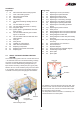
4:1 REPLACING THE PRINTED CIRCUIT
BOARD
1. Remove the cover and service panel on the boiler.
2. Detach the blue (N) (g. 7 A) and brown (R) (g. 7 B)
cables at the cable ports on the printed circuit board,
and remove the blue (N) (g. 7 C), brown (R) (g. 7 D)
and red (R) (g. 7 G) cables from the electrical heating
cartridge.
3. Detach the white 15-point connection block (g. 7 E)
from the printed circuit board.
4. Remove the screw behind the connection block (g 7H).
5. Remove the printed circuit board by pressing together
the hooks on the 5 plastic spacers (g. 7 F), and pulling
out the circuit board.
6. Push the new board rmly into the spacers and connect
the cables as shown in g. 7.
7. Ret the service door and cover and test-run the
electrical heating cartridge.
F
Fig 8.
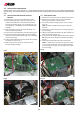
4:2 REPLACING FAN
1. Remove the cover and the service panel from the boiler.
2. Disconnect the positive (red, g. 8 A) and negative
(black, g. 8 B) cables on the fan motor.
3. Unscrew the plastic housing from the motor, 2 screws
(g. 8 C).
(NB! On boilers with wall ues (94x) item 3 shall be
ignored.)
4. Unscrew the 4 plate screws (g. 9 C) securing the fan to
the fan housing.
5. Tilting the fan towards the boiler body, lift it upwards out
of the fan housing (see g. 10).
6. Fit the new fan by following these instructions in reverse.
NB! Take care not to damage the impeller when tting
the fan.
7. Fit the service panel and lid and test-run the boiler.
(NB! In a small number of boilers, the gas pipe is tted
in such a way that the fan cannot be extracted without
rst removing the gas pipe. Do not forget to check that
the seal is tight).
C