ALD-10764 220515 Antennes satellites automatiques ALDEN ALDEN automatische Sat-Anlagen ALDEN automatic satellite systems Guide d’installation Aufbau-Anleitung Installation guide Onelight 65 Orbiter 65 Orbiter 85 Onelight 60 Platinium Orbiter 80 Platinium Planar® AS2® AS3® AS4® modèles déposés - photos non contractuelles - document établi sous réserve de modifications techniques Geschütztes Model - Technische Änderungen vorbehalten.
Avertissements La reproduction de tout ou partie de ce guide est interdite sans un accord écrit de la part d’ALDEN. ALDEN attire une attention particulière sur les risques encourus en cas de montage non conforme. La responsabilité d’ALDEN ne pourra être engagée en cas de montage non conforme aux règles de l’art et en particulier si l’installation est effectuée par un non-professionnel. Le revendeur est réputé connaître les règles de l’art et s’y conformer.
Pour une image de qualité, n’utilisez pas les circuits de câbles coaxiaux existants. De manière générale, il est indispensable d’éviter tout raccord. Il est impératif de tirer une alimentation séparée et équipée d’un fusible 5 Ampères directement depuis la batterie cellule pour alimenter le terminal de réception / AIO®.
Avertissements avant installation Ne jamais brancher vos équipements satellites (SSC®, démodulateur) sur une ligne commandée par la centrale. Dans tous les cas, Alden recommande une ligne directe sur la batterie avec un fusible de 5 A.
Installation de l’antenne A. Emplacement sur le toit. Une antenne satellite doit toujours se replier vers l’arrière du véhicule, jamais vers l’avant ou sur le coté. Si possible, installez l’unité sur une surface plane du véhicule. Évitez les parties bombées ou inclinées (par exemple la capucine). FAUX JUSTE Sens de conduite Sens de conduite B. Surface de rotation. Aucun obstacle ne doit se trouver dans la surface de rotation d’une antenne ou d’un panneau. (Exemples : lanterneaux, cheminées, équipements.
C. Vérification de la surface de rotation (présence / absence d’obstacles). Important : Il est impératif d’ouvrir tous les lanterneaux afin de vérifier correctement la surface de rotation. 1. Repérez l’endroit prévu sur le toit, LNB replié vers l’arrière du véhicule. 2. Marquez l’emplacement du centre de l’unité extérieure sur le toit à l’aide d’un crayon. 3. Coupez un morceau de ficelle de 60 cm. Placez l’une des extrémité au centre de l’unité repéré sur le toit.
Collage de l’unité extérieure de l’antenne : 1. À l’aide d’un crayon, marquez l’emplacement de l’unité extérieure de l’antenne sur le toit avant de la déplacer. 2. Poncez les surfaces à encoller (toit et dessous des pattes de fixation de l’unité extérieure de l’antenne) avec du papier à poncer (grain moyen). 3. Nettoyez, les surfaces à encoller. 4. À l’aide du tampon, étalez du SikaAktivator -205 sur les surfaces nettoyées. Temps de séchage : 15 à 20 minutes. 5.
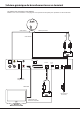
Schéma générique de branchement avec un terminal Pour antenne AS2®, Onelight, Orbiter, Planar®, Eurobird et Skymatic Ce schéma vous est fourni à titre indicatif. Référez-vous aux instructions accompagnant votre système de réception pour procéder aux branchements. Câble coaxial * ATTENTION pour l’antenne Planar®, utilisez l’atténuateur fourni 20dB.
Schéma générique de branchement avec un terminal Pour antenne AS3® et AS4® Ce schéma vous est fourni à titre indicatif. Référez-vous aux instructions accompagnant votre système de réception pour procéder aux branchements. 7,5A Câble moteur 7,5A BLEU BRUN Câble de puissance Câble coaxial ON S/PDIF OUT VIDEO IN IR OFF L USB R AUDIO DC12V/5A TV OUT Optionnel + HDMI TV DATA CONTACT MOTOR Câble HDMI 3A Capteur infrarouge déporté + après contact. (1,5A. min.
Schéma générique de branchement avec un A.I.O® Pour antenne AS2®, Onelight, Orbiter, Planar®, Eurobird et Skymatic Câble coaxial DATA MOTOR 3A LNB IN CI SLOT CONTACT POWER 12V USB SAT OFF Câble moteur ON * ATTENTION pour l’antenne Planar®, utilisez l’atténuateur fourni 20dB. + après contact. (1,5A. min.
Schéma générique de branchement avec un A.I.O® Pour antenne AS3® et AS4® 7,5A MOTOR CONTACT DATA 3A LNB IN CI SLOT OFF BLEU POWER 12V USB SAT ON 7,5A Câble moteur BRUN Câble de puissance Câble coaxial + après contact. (1,5A. min.
Installation avec un LNB Twin En fonction de votre équipement, se référer aux pages 8 à 11 pour le raccordement du câble moteur et le câble coaxial 1.
Utilisation de l’antenne Utilisée avec un récepteur ALDEN, un module de positionnement ALDEN ou un téléviseur AIO®, le positionnement de votre antenne face au satellite est entièrement automatisé. Veuillez vous référez au guide d’utilisation de votre récepteur ALDEN, module de positionnement ALDEN ou téléviseur AIO® pour connaître les différents étapes de mise en route et de repli de votre antenne automatique.
Échelle des vents À titre informatif, le tableau suivant présente la classification des vents. À partir d’un vent force 5, il est conseillé de replier vos équipements mobiles (panneaux solaires, antennes satellites). À partir d’un vent force 7, il est obligatoire de replier vos équipements mobiles.
Garantie ALDEN La garantie ALDEN couvre : Les garanties pour vice de fabrication sont accordées à partir de la date de facturation à l’acheteur sous réserve de renvoi du bon de garantie. À défaut de retour, cette garantie sera limitée dans le temps. Pour pouvoir bénéficier de la garantie des produits, il convient impérativement de conserver la facture d’achat du dit produit. Attention : Toute intervention sans accord écrit de la part de la SAS ALDEN entraîne de plein droit la nullité de la garantie.
Garantie ALDEN recommande de s’adresser aux professionnels pour tout montage. En cas d’installation personnelle, l’acheteur fera sienne les responsabilités affairant à la sécurité. L’acheteur est dans ce cas réputé avoir les compétences nécessaires. Il s’engage à respecter les règles usuelles qu’appliquent les professionnels. Il veillera à respecter les lois en vigueur dans le pays d’utilisation. Il ne déviera pas le produit de l’utilisation prévue.
Warnungen Die Vervielfältigung oder Teilvervielfältigung dieses Handbuches ist ohne eine schriftliche Zustimmung von Seiten der Firma ALDEN untersagt. ALDEN lehnt jegliche Verantwortung, welcher Natur diese auch sein möge, ab vor allem für jeden Unfall oder Vorfall im Falle der Nichtbeachtung der angegebenen Anweisungen, sowohl bei der Installation als auch bei der Bedienung. ALDEN hebt besonders die Risiken hervor, die bei einer nicht entsprechenden Montage entstehen können.
Vor jeder Fahrt, MUSS die Antenne bereits eingefahren sein. Folgen Sie dafür die üblichen Verfahrensweise zum Einfahren der Antenne. Überprüfen Sie vor der Abfahrt, dass die Antenne vollständig eingefahren ist. Solange der Einfahrvorgang noch nicht abgeschlossen ist, unterbrechen Sie niemals die Stromversorgung des AIO® / Receivers. Im Falle einer längeren Stilllegung des Fahrzeugs ist es empfehlenswert, die Sicherung für den Receiver/AIO und der Antenne herauszunehmen.
Vor der Installation Schließen Sie niemals die Anlagen (AIO®, S.S.C.® oder Receiver) an eine vorhandende Stromversorgung des Aufbaus im Wohnmobil. Alden schreibt ausdrücklich vor, dass der 12V-Anschluss direkt an der Bordbatterie mit einer 5Ah Sicherung zu machen ist. Sollte das nicht möglich sein, stellen Sie sicher, dass der Ein/Aus-Schalter des AIO® für den Benutzer zugänglich ist. Informieren Sie den Benutzer, den AIO® auszuschalten, wenn er nicht in Benutzung ist.
Aufbau der Sat-Anlage A. Aufbaustelle auf dem Dach. Eine Sat-Antenne muß sich immer in entgegengesetzter Fahrtrichtung des Fahrzeuges schließen. Nie nach Vorne oder zur Seite. Wenn möglich, installieren Sie die Anlage auf eine ebene Fläche. Vermeiden Sie gewölbte und schiefe Ebene. FAUX JUSTE Fahrtrichtung Fahrtrichtung B. Drehradius. Kein Gegenstand darf sich auf dem Drehradius einer Antenne oder einem Solar-Panel befinden. (Zum Beispiel: Dachfenster, Rohre, sonstige Ausrüstungen...
C. Kontrolle der Drehfläche. Hinweis: Alle Oberlichter sowie andere Elemente sollten ausgefahren sein. 1. Positionnieren Sie sich auf der gewünschten Montagestelle. 2. Markieren Sie die Mitte der Montagestelle mit einem Bleistift. 3. Halten Sie eine 60cm lange Schnur an dem markierten Punkt fest und machen Sie eine komplette Umdrehung mit der ausgestreckten Schnur um zu prüfen, dass keine Hinternisse die Antenne stören werden. D. Befestigung der Antenne.
Außeneinheit an die Antenne kleben: 1. Markieren Sie mit Hilfe eines Bleistifts, die Stelle der Antenne auf dem Dach. 2. Schmirgeln Sie die zu klebenden Flächen (Dach und unter den Befestigungsfüßen der Außeneinheit der Antenne) mit Schmirgelpapier ab (durchschnittliches Korngröße). 3. Reinigen Sie mit einem Verdünnungsmittel, die zu klebenden Flächen. 4. Rollen Sie den SikaAktivator -205 mit Hilfe des Deckels auf den gereinigten Flächen aus. Trockenzeit : 15 bis 20 Minuten. 5.
Allgemeine Anschlussplan mit Steuerreceiver Nur AS2®, Onelight, Orbiter, Planar®, Eurobird und Skymatic Koaxialkabel * ACHTUNG: Bitte den Attenuator -20dB auf den Koaxial Kable anschließen. Motorkabel SAT IN SAT OUT L VIDEO IR ON HDMI R COAXIAL TV OUT optional TV SCART OFF 9/16V DC CONTACT DATA MOTOR HDMI-Kabel 12V Stromversorgung für den Fernseher + nach Kontakt. (D+) Mindestens 1,5A.
Allgemeine Anschlussplan mit Steuerreceiver Nur AS3® und AS4® BRAUN Steuerkabel 7,5A Motorkabel 7,5A BLAU Koaxialkabel SAT IN SAT OUT L VIDEO IR ON HDMI R COAXIAL TV OUT optional TV SCART OFF 9/16V DC CONTACT DATA MOTOR HDMI-Kabel 12V Stromversorgung für den Fernseher + nach Kontakt. (D+) Mindestens 1,5A.
Allgemeine Anschlussplan mit A.I.O® Nur AS2®, Onelight, Orbiter, Planar®, Eurobird und Skymatic Koaxialkabel * ACHTUNG: Bitte den Attenuator -20dB auf den Koaxial Kable anschließen. Motorkabel RF TV TV SCART USB SAT DATA SAT IN 3A CI SLOT VGA HDMI MOTOR POWER 12 V + nach Kontakt. Mindestens 1,5A.
Allgemeine Anschlussplan mit A.I.O® Nur AS3® und AS4® 7,5A BLAU 7,5A Motorkabel BRAUN Steuerkabel Koaxialkabel RF TV TV SCART USB SAT DATA SAT IN 3A CI SLOT VGA HDMI MOTOR POWER 12 V + nach Kontakt. Mindestens 1,5A.
Montage einer TWIN-Anlage Bitte folgen Sie der Anweisung auf Seite 23-26 um das Motorund Koaxialkabel 1 zu verbinden. Koaxialkabel 1 Koaxialkabel 2 Motorkabel SAT IN SAT OUT L VIDEO IR ON HDMI R COAXIAL TV OUT optional OFF 9/16V DC TV SCART HDMI-Kabel 12V Stromversorgung für den Fernseher externer IREmpfänger SAT IN SAT OUT L VIDEO IR ON HDMI R COAXIAL TV OUT optional TV SCART OFF 9/16V DC CONTACT DATA MOTOR HDMI-Kabel 12V Stromversorgung für den Fernseher + nach Kontakt.
Inbetriebnahme der Antenne Bei einer Benutzung mit einem ALDEN-Receiver oder einen ALDEN-Sat-Suchmodul (S.S.C.®), funktionniert die Suche nach dem Satelliten vollautomatisch. Für weitere Erklärungen und Hinweise, lesen Sie die Anleitung des Receivers oder S.S.C.®-Moduls. Was machen im Fall einer Störung? Bei Stromausfall Die Antenne findet den Satelliten nicht 28 Überprüfen Sie Sicherungen.
Windskala Die folgende Tabelle stellt die Klassifikation der Winde dar. Ab einer Windstärke von 5 wird empfohlen, die beweglichen Ausrüstungen einzufahren (Sonnenkollektoren, Satellitenantennen). Ab einer Windstärke von 7 müssen die beweglichen Ausrüstungen eingefahren werden.
Garantie ALDEN Die ALDEN-Garantie: Über der gesetzlichen Gewährleistung hinweg, garantiert ALDEN seine Geräte insgesammt 3 Jahre mindestens (nach Rechnungsdatum). Die Garantie sowie die Gewährleistung ist nur möglich, wenn die Rechnung vorliegt. Achtung: Jeder Eingriff, der ohne schriftliche Vereinbarung von Seiten der SAS ALDEN durchgeführt wird, führt zur Nichtigkeit der Garantie. Dem Kunden und dem Käufer steht keine Entschädigung zu, welcher Art sie auch sein möge.
Garantie ALDEN empfiehlt die Montage von Fachleuten durchführen zu lassen. Wenn der Käufer selbst die Montage durchführt, ist dieser für die Sicherheit verantwortlich. In diesem Fall heißt es, dass der Käufer über die notwendigen Kompetenzen verfügt. Er verpflichtet sich, die, von den Fachleuten angewendeten, gebräuchlichen Regeln und die im Anwendungsland geltenden Gesetze zu achten. Er verwendet das Produkt nur zum vorgesehenen Zweck. Garantie : Im Störungsfall, kontaktieren Sie Ihren Händler.
Warning The reproduction of whole or part of this guide is strictly forbidden without Aldens agreement. Alden draws your attention to the risks that may occur if the mounting is not correct. Alden declines all responsability if the product is not mounted in the correct way and especially if it is installed by a non professional person. The retailer is ment to know installation rules and to apply them.
For a good quality picture, do not use the existing coax. cable circuits. Generally, it is recommanded to avoid all connections. You must provide a separate power supply equipped with a 5 Amp. fuse directly from the board battery to the S.S.C®/receiver/A.I.O®. You must provide a separate power supply equipped with a 3 Amp. fuse directly from the main electric board to the S.S.C®/receiver/A.I.O® for the Plus after ignition connection (only with Alden automatic satellite systems).
Warning before installation Protect the 3 cables (motor, skew and coax) with rubber grommets when installing through holes, walls and cavities.Also protect the end of each cable with papertape during installation. You MUST use the provided cables, without cutting nor modifying them. If not, the warranty will become void. Do not use the existing coax cables in the vehicle, as the quality of the reception can be altered. Each joint or different types of cables may weaken the quality of reception signal.
Installation A. Location on the roof. A satellite system must always be folded down towards the back of the vehicle, never to the front nor to the sides. If possible, always install the system on a smooth and flat surface and avoid curves or inclinations. FAUX JUSTE Sens de conduite Sens de conduite B. Rotation area. No obstacle must be in the surface of rotation of a satellite system or a solar panel. (Examples: roof vents, equipments...
C. Controlling the rotation area (presence / absence of obstacles). Important : To check the rotation area, open all the roof vents. 1. Install the unit on the roof on the chosen location, the LNB has to be folded towards the back of the vehicle. 2. By using a pencil, mark the location of the unit, then remove the unit. 3. Mark the center of the drawing. 4. Cut a piece of string of 60 cm long. Place one end at the center of the drawing.
How to glue the outside unit: 1. Mark the location of the external unit with a pencil. Now remove the external unit from the roof. 2. Sand the surface you must glue (roof, under the two fixation plates of the external unit) with sandpaper (medium grain). 3. Clean each surface with a thinner. 4. Spread SikaAktivator -205 on the sanded surface. Leave to dry for 15 to 20 minutes. 5. Glue generously the fixation plates of the external unit with SikaFlex -521 UV then press slightly on the unit.
Main connection layout with a receiver For AS2®, Onelight, Orbiter, Planar®, Eurobird and Skymatic Coaxial cable * WARNING: On Planar® system, install the Attenuator -20dB provided on the coaxial cable. Motor cable SAT IN SAT OUT L VIDEO IR ON HDMI R COAXIAL TV SCART TV OUT optional OFF 9/16V DC CONTACT DATA MOTOR HDMI cable Power supply for compatible television + after ignition (min. 1,5A.
Main connection layout with a receiver For AS3® and AS4® 7,5A 7,5A Motor cable SAT IN SAT OUT L VIDEO IR ON HDMI R COAXIAL TV SCART TV OUT optional BROWN Power cable BLUE Coaxial cable OFF 9/16V DC CONTACT DATA MOTOR HDMI cable Power supply for compatible television + after ignition (min. 1,5A.
Main connection layout with an A.I.O® For AS2®, Onelight, Orbiter, Planar®, Eurobird and Skymatic Coaxial cable * WARNING: On Planar® system, install the Attenuator -20dB provided on the coaxial cable. Motor cable RF TV TV SCART USB SAT DATA SAT IN 3A CI SLOT VGA HDMI MOTOR POWER 12 V + after ignition (min. 1,5A.
Main connection layout with an A.I.O® For AS3® et AS4® 7,5A BLUE 7,5A Motor cable BROWN Power cable Coaxial cable RF TV TV SCART USB SAT DATA SAT IN 3A CI SLOT VGA HDMI MOTOR POWER 12 V + after ignition (min. 1,5A.
Installation with LNB Twin Please refer instructions page 38 to 41 to connect the Motor and coaxial cable 1. Coaxial cable 1 Coaxial cable 2 Motor cable L SAT IN SAT OUT VIDEO IR ON HDMI R COAXIAL TV OUT optional OFF 9/16V DC TV SCART HDMI cable Power supply for compatible television External IR sensor SAT IN SAT OUT L VIDEO IR ON HDMI R COAXIAL TV SCART TV OUT optional OFF 9/16V DC CONTACT DATA MOTOR HDMI cable Power supply for compatible television + after ignition (min.
Using the satellite system When using an Alden receiver, AIO® or SSC®, the positionning of the main unit will be done automatically. Read the user’s guide of the receiver, AIO®, SSC® to find out more about starting, closing your automatic satellite system. In case of breakdown No more power supply Check the connections, cables and fuses.Fold the system down and use as usual. The system will not find the satellite Make sure there is nothing facing the dish (building, tree...).
Wind classification When the wind gets to 5, we advice to fold your mobile equipment down (solar panel, satellite systems). When it gets to 7, you MUST fold everything down.
ALDEN warranty The Alden warranty covers: This product is warranted by SAS Alden to be free of manufacturing faults for two years from the date of purchase of the buyer. To benefit from this warranty, you MUST keep the invoice corresponding to the purchase of this product. Warning: Do not attempt to interfer on the product without a written agreement from Alden: if you still decide to do so, the warranty will be void.
Warranty Alden recommends that the installation be done by a professional. If you choose to install the product yourself, you will be responsible for security. In this case,you are ment to have the necessary competence. You will have to respect rules that are applied to professional installers. Respect the law. The product will only be used for the intended matter. Warranty: The buyer will contact his retailer if problems occur with the product.