
Installation & Assembly


9
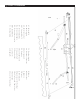
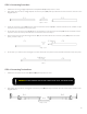
STEP 6: Roller Support Assembly
1. Find the inner square shaft (F-1) located in the roller tube. Insert this into the square hole of the gear box, as shown
in step 1 on the diagram below.
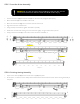
Steps 6 - 9
Steps 4 and 5
Roller
Front bar
M
Step 1
Insert in
F-1
D
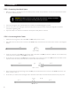
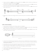
2. Using a mallet, knock the round shaft cover (E) into the right roller support (D).
3. Now, link the roller support into the round shaft (F-2) using a mallet to tap it into place.
4. Use a wrench to tighten the bolt of the roller support.
Insert in
F-2
D
E
Steps 2, 3, 4
Step 5
5. At this point, the roller tube and the roller support will be fully secured together, as shown in step 5 on the diagram
below.