
Installation Guide


7
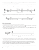
STEP 3: Connecting Front Bars
1. Gather the two long, wedge-shaped front bars (C-1 and C-2) and lay them in a line.
2. Also gather the one short, wedge-shaped connection piece (C-3) and lay it between the two front bars, as seen in the
diagram below.
STEP 4: Connecting Torsion Bars
1. Gather the two white torsion bars (B-1 and B-2) and lay them in a line.
3. Insert the connector piece (C-3) into the interior end of the front bar (C-2). If insertion is dicult, use a mallet to tap it
into place. Once inserted, screw it into place.
4. At this time, the connector piece (C-3) will be connected to one of the two front bars (C-2) and secured with screws.
A portion of the connector piece will stick out of the front bar until step 5.
5. Now, connect the second remaining front bar (C-1) to the other side of the connector piece (C-3) and screw it into
place, just like in step 3.
2. Also gather the one short, rectangular connection piece (B-3) and lay it between the two torsion bars, as seen in the
diagram below.
6. At this time, you will have one full-length front bar, with both arm pieces connected and screwed securely into place.
WARNING DO NOT REMOVE THE SAFETY SLEEVES THAT HOLD THE ARMS DOWN!
C-1 C-3 C-2
Steps 1 and 2
C-1 C-3 C-2
A-A-1
Steps 3, 4, 5
C-1 C-2
Step 6
A-A-1
B-1 B-2
Steps 1 and 2
B-3