
Instructions / Assembly


7
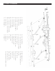
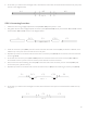
8. At this time, you will have one full-length roller, with all three roller tubes connected and screwed securely into place,
as seen in the diagram below.
A-1 A-3 A-2
Step 8
STEP 3: Connecting Front Bars
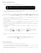
1. Gather the three long, wedge-shaped front bars (C-1, C-2, C-3) and lay them in a line.
2. Also gather the two short, wedge-shaped connection pieces (C-C-1, C-C-2) and lay one between C-1 and C-3, and the
other between C-3 and C-2, as seen in the diagram below.
3. Insert the connector piece (C-C-1) into the interior end of the front bar on the left (C-1). If insertion is dicult, use a
mallet to tap it into place. Once inserted, screw it into place.
4. Repeat this process on the other side; insert the other connector piece (C-C-2) into the interior end of the front bar
on the right (C-2).
5. At this time, the connector pieces (C-C-1, C-C-2) will be connected to each of the outer front bars (C-1, C-2) and
secured with screws. A portion of the connector pieces will stick out of the front bars.
6. Now, connect the third remaining front bar (C-3) to the other side of the connector piece on the left (C-C-1) and
screw it into place, just like in step 3.
7. Repeat this process on the other side; connect the other front bar (C-3) to the remaining connector piece (C-C-2).
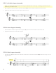
8. At this time, you will have one full-length front bar, with all three front bar pieces connected and screwed securely
into place.
C-1 C-C-1 C-3 C-C-2 C-2
Steps 1 and 2
Step 8
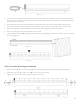
C-1 C-3 C-2
Steps 3 - 7
C-1 C-C-1 C-3 C-C-2 C-2