WAE-WYE SERIES SINGLE SPLIT DC INVERTER AIR CONDITIONER / HEAT PUMP SYSTEMS Mono DC SERVICE MANUAL Parker Davis HVAC International, Inc. Revision A: 1312030001, Content updated. 2260 NW 102nd Place, Doral, FL 33172 Ph: (305) 513-4488 Cooling Only Model Numbers (Indoor + Outdoor Units): WAE009AMFI15RL (WE009AMFI15CLD + AN009AMFI15RPD) info@pd-hvac.
CONTENTS 1. Precaution ................................................................................................................................................. 1 1.1 Safety Precaution ........................................................................................................................ 1 1.2 Warning ....................................................................................................................................... 1 2. Part Names And Functions .................
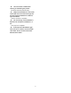
Sharp edges could cause injury, be especially careful of the case edges and the fins on the condenser and evaporator. 1. Precaution For installation, always contact the dealer or an authorized service center. Do not install the product on weak or defective structures or stands. Be sure the installation area does not deteriorate with age. If the base collapses, the air conditioner could fall with it, causing property damage, product failure, and personal injury. 1.
There is risk of electric shock or fire. product. To avoid vibration of water leakage. Stop operation and disconnect the power during storm or hurricane. If possible, further secure the product before the hurricane arrives. There is risk of property damage, failure of product, or electric shock. Do not install the product where the noise or hot air from the outdoor unit could disturb the neighbors. It may cause disturbance for your neighbors.
Use a firm stool or ladder when cleaning or maintaining the product. Be careful and avoid personal injury. Replace the all batteries in the remote control with new ones of the same type. Do not mix old and new batteries or different types of batteries. There is risk of fire or explosion. Do not recharge or disassemble the batteries. Do not dispose of batteries in a fire. They may burn of explode. If the liquid from the batteries gets onto your skin or clothes, wash it well with clean water.
2. Part Names And Functions 2.
2.
2.3 Functions of Indoor/Outdoor units Filter Cold Catalyst Filter Ionizer(O) Silver Ion Filter Louver Position Memory Function Vitamin C Filter(O) Refrigerant Leakage Detect 3M HAF Filter(O) 8 Degree Heating(O) Bio Filter(O) Heat Compensation(O) Golden Fin(O) Self-diag.
Cold Catalyst Filter: Eliminate formaldehyde and other volatile organic compounds as well as harmful gases and odors. Ionizer: Release negative ions, eliminate odor, dust, smoke and pollen particles to give you fresh and healthy air. Silver Ion Filter: Sterilize bacteria effectively by decomposing cell wall of bacteria. Vitamin C Filter: Release Vitamin C which can eliminate active oxygen to beautify the skin.
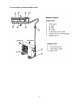
3. Dimension 3.1 Indoor Unit H D W Model W D H 680mm (26.8in) 178mm (7.0in) 255mm (10.0in) 770mm (30.3in) 188mm (7.4in) 255mm (10.0in) 905mm (35.6in) 198mm (7.8in) 275mm (10.8in) 1030mm (40.6in) 218mm (8.6in) 315mm (12.
L R H Model WE009AMFI15CLD WE009AMFI15HLD WE009GMFI15HLD R L H 92mm (3.6in) 170mm (6.7in) 45mm (1.8in) 95mm (3.7in) 170mm (6.7in) 45mm (1.8in) 80mm (3.1in) 100mm (3.9in) 45mm (1.8in) Dimension of installation hole WE012AMFI15CLD WE012AMFI15HLD WE012GMFI15CLD Φ65mm(2.56in) WE012GMFI15HLD WE018GMFI15CLD WE018GMFI15HLD R L H Model R L H Dimension of installation hole WE024GMFI15CLD 163mm (6.4in) 293mm (11.5in) 45mm (1.8in) Φ65mm(2.
4.2 Outdoor Unit More than 30cm(11.8in) More than 30cm(11.8in) More than 60cm(23.6in) ︶ (Service space Fe n o b ce o st a r cle s More than 60cm(23.6in) More than 70cm(27.6in) Note: The above drawing is only for reference. The appearance of your units may be different. Model W H D W1 A B YN009GMFI15RPD 700mm (27.6in) 240mm (9.4in) 540mm (21.3in) 757mm (29.8in) 458mm (18.0in) 250mm (9.8in) 660mm 265mm 540mm 732mm 458mm 276mm (26.0in) (10.4in) (21.3in) (28.8in) (18.0in) (10.
660mm 265mm 540mm 732mm 458mm 276mm (26.0in) (10.4in) (21.3in) (28.8in) (18.0in) (10.9in) YN012GMFI15RPD 780mm (30.7in) 250mm (9.8in) 540mm (21.3in) 843mm (33.2in) 549mm (21.6in) 276mm (10.9in) AN012GMFI15RPD 780mm (30.7in) 250mm (9.8in) 540mm (21.3in) 843mm (33.2in) 549mm (21.6in) 276mm (10.9in) 760mm 285mm 590mm 823mm 530mm 290mm (29.9in) (11.2in) (23.2in) (32.4in) (20.9in) (11.4in) 760mm 285mm 590mm 823mm 530mm 290mm (29.9in) (11.2in) (23.2in) (32.4in) (20.
4.
For heat pump models: INDOOR OUTDOOR CHECK VALVE (Heating Model only) LIQUID SIDE 2-WAY VALVE CAPILIARY TUBE HEAT EXCHANGE (EVAPORATOR) HEAT EXCHANGE (CONDENSER) GAS SIDE REVERSING VALVE (Heating Model only) 3-WAY VALVE ACCUMULATOR COOLING COMPRESSOR 13 HEATING
5. Wiring Diagram 5.
9000 BTU, 115V, Cool Only / 9000 BTU, 115V, Heat Pump 12000 BTU, 115V, Cool Only / 12000 BTU, 115V, Heat Pump 18000 BTU, 230V, Cool Only / 18000 BTU, 230V, Heat Pump 15
24000 BTU, 230V, Cool Only / 24000 BTU, 230V, Heat Pump 16
5.
18000 BTU, 230V, Cool Only / 18000 BTU, 230V, Heat Pump 24000 BTU, 230V, Cool Only / 24000 BTU, 230V, Heat Pump 18
For 9000 BTU, 230V, Heat Pump / 12000 BTU, 230V, Cool Only / 12000 BTU, 230V, Heat Pump: For 9000 BTU, 115V, Cool Only / 9000 BTU, 115V, Heat Pump / 12000 BTU, 115V, Cool Only / 12000 BTU, 115V, Heat Pump: 19
For 18000 BTU, 230V, Cool Only / 18000 BTU, 230V, Heat Pump: For 24000 BTU, 230V, Cool Only / 24000 BTU, 230V, Heat Pump: 20
6.3 Pipe length and the elevation 6 Installation Details Pipe size 6.1 Wrench torque sheet for installation Outside diameter Models Gas Torque torque Ф6.35mm 1/4in 1500N.cm (11 Lbf.Ft). 1600N.cm (12 Lbf.Ft.) Ф9.52mm 3/8in 2500N.cm (18 Lbf.Ft.) 2600N.cm (19 Lbf.Ft) Ф12.7mm 1/2in 3500N.cm (26 Lbf.Ft) 3600N.cm (27 Lbf.Ft) Ф15.9mm 5/8in 4500N.cm (33 Lbf.Ft) 4700N.cm (35 Lbf.Ft) Ф19mm 3/4in Liquid Additional tightening 6500N.cm (48 Lbf.Ft.
WE012GMFI15HLD + YN012GMFI15RPD WE018GMFI15CLD + AN018GMFI15RPD WE018GMFI15HLD + YN018GMFI15RPD WE024GMFI15CLD + AN024GMFI15RPD WE024GMFI15HLD + YN024GMFI15RPD 7.5m 10m 25m 15g/m (24.6ft) (32.8ft) (82.0ft) (0.16oz/ft) 7.5m 20m 30m 15g/m (24.6ft) (65.6ft) (98.4ft) (0.16oz/ft) 7.5m 20m 30m 15g/m (24.6ft) (65.6ft) (98.4ft) (0.16oz/ft) 7.5m 25m 50m 30g/m (24.6ft) (82.0ft) (164ft) (0.32oz/ft) 7.5m 25m 50m 30g/m (24.6ft) (82.0ft) (164ft) (0.
6.4 Installation for the first time 5) Operate the vacuum pump to evacuate. 6) Make evacuation for 30 minutes and check whether the compound meter indicates -0.1Mpa(14.5Psi). If the meter does not indicate -0.1Mpa(14.5Psi) after pumping 30 minutes, it should be pumped 20 minutes more. If the pressure can’t achieve -0.1Mpa(14.5Psi) after pumping 50 minutes, please check if there are some leakage points. Fully close the Low side valve of the manifold and stop the vacuum pump.
2). Purge the air from the charge hose. Open the valve at the bottom of the cylinder and press the check valve on the charge set to purge the air (be careful of the liquid refrigerant). 3) Put the charging cylinder onto the electronic scale and record the weight. 4) Operate the air conditioner at the cooling mode. 5) Open the valves (Low side) on the charging manifold set and charge the system with liquid refrigerant. 6).
manifold hose with the push pin to the 3-way valve's gas service port. 3). Air purge of the charge hose. Open the Low side valve of the manifold slightly to purge air from the charge hose for 5 seconds and then close it quickly. 4). Set the 2-way valve to the close position. 5). Operate the air conditioner at the cooling cycle and stop it when the gauge indicates 0.1Mpa(14.5Psi). 6). Set the 3-way valve to the closed position immediately Do this quickly so that the gauge ends up indicating 0.3Mpa(43.
2. Refrigerant charging Procedure: 1). Connect the charge hose to the charging cylinder, open the 2-way valve and the 3-way valve Connect the charge hose which you disconnected from the vacuum pump to the valve at the bottom of the cylinder. If the refrigerant is R410A, make the cylinder upside down to ensure liquid charge. 2).
7.
8. Electronic Function 8.1 Abbreviation T1: Indoor room temperature T2: Coil temperature of evaporator T3: Coil temperature of condenser T4: Outdoor ambient temperature T5: Compressor discharge temperature 8.2 Display function 8.2.1 Icon explanation on indoor display board.
8.3 Main Protection recently or if T4<3℃ and compressor has stopped for over 3 hours, the compressor heating circuit will activate. Preheating mode: A weak current flow through the coil of compressor through the wiring terminal of the compressor, then the compressor is kept warm without operating. Preheating release condition: If T4>5℃ or the compressor starts running, the preheating function will stop. 8.3.
8.4 Operation Modes and Functions Fmax: The maximum operation frequency of compressor. F1~F8: The detailed value of the compressor operation frequency. If users switch on the unit by remote controller, the compressor will run at the Fmax frequency for 7 minutes according to the outdoor ambient temp. During the 7 minutes, the frequency limitation is active. 7 minutes later, the compressor running frequency will be controlled as below: 8.4.1 Fan only mode (1) Outdoor fan and compressor stop.
Off I3COOL 4 High Decrease 3 I2COOL Medium 1.5 1 Hold I1COOL Low Resume 8.4.3 Heating Mode 8.4.3.1 Compressor running rules The maximum operation frequency of the compressor after starting is based on the following rule. I3COOL, I2COOL,I1COOL mean different running current value. Off: Compressor stops. Decrease: Decrease the running frequency to the lower level. Hold: Keep the current frequency. Resume: No limitation for frequency.
temp. During the 7 minutes, the frequency limitation is active. 7 minutes later, the compressor running frequency will be controlled as below: Off I3HEAT Decrease I2HEAT H H +5.0 Hold I1HEAT +4.5 G +3.5 +3.0 F +2.5 E +2.0 D +0.5 I3HEAT, I2HEAT,I1HEAT mean different running current value. Off: Compressor stops. Decrease: Decrease the running frequency to the lower level. Hold: Keep the current frequency. Resume: No limitation for frequency. C +1.5 +1.
The units run with T3<3℃ for 80 minutes and T3 stays lower than TCDI+2℃ for more than 3 minutes. ----T4<0℃, If the 1st condition and 2nd condition items are satisfied, then the program judges if T2 has decreased more than 5℃. When T2 has decreased more than 5℃, system will enter the defrost mode.
The louver operates same as in relevant mode. If the machine switches mode between heating and cooling, the compressor will stop for 15 minutes and then choose mode according to T1-Ts. If the setting temperature is modified, the machine will re-determine the running function again. For 18k, 24k models: Frequency F2 Frequency F8 Compressor 4-way valve Outdoor fan Indoor fan on off on off 8.4.5 Drying mode 8.4.5.1 Indoor fan speed is fixed at breeze speed and can’t be changed.
8.4.6.2 In forced operation mode, all general protections and remote control is available. 8.4.6.3 Operation rules: Forced cooling mode: The compressor runs at F2 frequency and indoor fan runs as breeze speed. After running for 30 minutes. the machine will turn to auto mode with 24℃ setting temperature. Forced auto mode: The action of forced auto mode is the same as normal auto mode with 24℃ setting temperature.
9. Troubleshooting Safety Electricity power is still kept in capacitors even the power supply is shut off. Do not forget to discharge the electricity power in capacitor. Electrolytic Capacitors (HIGH VOLTAGE! CAUTION!) For other models, please connect discharge resistance (approx.100Ω 40W) or soldering iron (plug) between +, terminals of the electrolytic capacitor on the contrary side of the outdoor PCB. Note: The picture above is only for reference. The plug of your side may be different.
9.
9.2 Outdoor unit error display For 9000 BTU, 230V, Heat Pump / 12000 BTU, 230V, Cool Only / 12000 BTU, 230V, Heat Pump: There’s a LED light on the outdoor PCB which is blue color. After power on, it will be slow flash (once 5 secs) when the unit is in standby and quick flash (2.5 per sec) if the unit has some problems.
For 9000 BTU, 115V, Cool Only / 9000 BTU, 115V, Heat Pump / 12000 BTU, 115V, Cool Only / 12000 BTU, 115V, Heat Pump: There’s a LED light on the outdoor PCB which is blue color. After power on, it will be slow flash (once 5 secs) when the unit is in standby and quick flash (2.5 per sec) if the unit has some problems.
For 18000 BTU, 230V, Cool Only / 18000 BTU, 230V, Heat Pump: LED1 (red) LED2 (yellow) LED3 (green) & LED4 (red) standby operating LED2 slow flashing on LED1 on on The picture of PCB above is only for reference. LED 1 is a red light and for the PCB POWER display. LED 2 is a yellow light. After power on, it will be slow flash (once every 5 secs) when the unit is in standby and quick flash (2.5 per sec) if the unit has some problems, it will be always on when the unit is in operation.
No. Problems LED3 (Green) LED4 (Red) 1 standby for normal O X 2 Operation normal X O 3 IPM malfunction or IGBT over-strong current protection ☆ X P0 4 Over voltage or too low voltage protection O O P1 5 Over voltage or too low voltage protection O ☆ P1 6 Inverter compressor drive error X ☆ P4 7 Inverter compressor drive error ☆ O P4 8 Inverter compressor drive error ☆ ☆ P4 O(light) X(off) IU display ☆(2.
9.3 Diagnosis and Solution 9.3.1 EEPROM parameter error diagnosis and solution(E0/F4) Error Code E0/F4 Malfunction decision Indoor or outdoor PCB main chip does not receive feedback conditions from EEPROM chip. Supposed causes ● Installation mistake ● PCB faulty Trouble shooting: Shut off the power supply and turn it on 5 seconds later. Is it still displaying the error code ? Yes If the EEPROM chip is welded on main PCB, replace the main PCB directly.
9.3.2 Indoor / outdoor unit’s communication diagnosis and solution(E1) Error Code E1 Malfunction decision Indoor unit does not receive the feedback from outdoor unit during conditions 110 seconds and this condition happens four times continuously. Supposed causes ● Wiring mistake ● Indoor or outdoor PCB faulty Trouble shooting: Power off, then turn on the unit 5 seconds later(reconnect the power wire).
Remark: Use a multimeter to test the DC voltage between L2 (or N on 115 V Models) port and S port of outdoor unit. The red pin of multimeter connects with L2 (or N on 115 V Models) port while the black pin is for S port. When AC is normally running, the voltage will move alternately between -50V to 50V. If the outdoor unit has malfunction, the voltage will move alternately with positive value. While if the indoor unit has malfunction, the voltage will be a certain value.
9.4.3 Zero crossing detection error diagnosis and solution(E2) Error Code E2 Malfunction decision When PCB does not receive zero crossing signal feedback for 4 conditions minutes or the zero crossing signal time interval is abnormal.
9.4.4 Fan speed has been out of control diagnosis and solution(E3) Error Code E3 Malfunction decision When indoor fan speed stays too low (<300RPM) for certain time, conditions the unit will stop and the LED will display the failure.
Index 1: 1.Indoor AC fan motor Measure the resistance value of each winding by using the tester. For the definite value of the resistance, refer to page 61 and page 64. Index2: 1: Indoor AC fan motor Power on and set the unit running in fan mode at high fan speed. After running for 15 seconds, measure the voltage of pin1 and pin2. If the value of the voltage is less than 100V (208~240V power supply) or 50V (115V power supply), the PCB must have problems and need to be replaced.
9.4.5 Open circuit or short circuit of temperature sensor diagnosis and solution(E5) Error Code E5 Malfunction decision If the sampling voltage is lower than 0.06V or higher than 4.94V, conditions the LED will display the failure.
9.4.6 Refrigerant Leakage Detection diagnosis and solution(EC) Error Code EC Malfunction decision Define the evaporator coil temp.T2 of the compressor just starts conditions running as Tcool. In the beginning 5 minutes after the compressor starts up, if T2 <Tcool-2℃ does not keep continuous 4 seconds and this situation happens 3 times, the display area will show “EC” and AC will turn off. Supposed causes ● T2 sensor faulty ● Indoor PCB faulty ● System problems, such as leakage or blocking.
9.4.7 IPM malfunction or IGBT over-strong current protection diagnosis and solution(P0) Error Code P0 Malfunction decision When the voltage signal that IPM send to compressor drive chip conditions is abnormal, the display LED will show “P0” and AC will turn off.
P-U P-V 51
P-W P-N 52
9.4.8 Over voltage or too low voltage protection diagnosis and solution(P1) Error Code P1 Malfunction decision An abnormal voltage rise or drop is detected by checking the conditions specified voltage detection circuit. Supposed causes ● Power supply problems. ● System leakage or block ● PCB faulty Trouble shooting: Check if the power supply is normal. No Disconnect the unit with power supply and try to restart the unit when power supply gets normal .
9.4.9 High temperature protection of compressor top diagnosis and solution(P2) Error Code P2 Malfunction decision If the sampling voltage is not 5V, the LED will display the failure. conditions Supposed causes ● Power supply problems.
9.4.10 Inverter compressor drive error diagnosis and solution(P4) Error Code P4 Malfunction decision An abnormal inverter compressor drive is detected by a special conditions detection circuit, including communication signal detection, voltage detection, compressor rotation speed signal detection and so on.
Main parts check 1. Temperature sensor checking Disconnect the temperature sensor from PCB, measure the resistance value with a tester. Temperature Sensors. Room temp.(T1) sensor, Indoor coil temp.(T2) sensor, Outdoor coil temp.(T3) sensor, Outdoor ambient temp.(T4) sensor, Compressor discharge temp.(T5) sensor. Measure the resistance value of each winding by using the multi-meter.
Appendix 1 Temperature Sensor Resistance Value Table for T1,T2,T3,T4 (℃--K) ℃ ℉ K Ohm ℃ ℉ K Ohm ℃ ℉ K Ohm ℃ ℉ K Ohm -20 -4 115.266 20 68 12.6431 60 140 2.35774 100 212 0.62973 -19 -2 108.146 21 70 12.0561 61 142 2.27249 101 214 0.61148 -18 0 101.517 22 72 11.5 62 144 2.19073 102 216 0.59386 -17 1 96.3423 23 73 10.9731 63 145 2.11241 103 217 0.57683 -16 3 89.5865 24 75 10.4736 64 147 2.03732 104 219 0.56038 -15 5 84.
Appendix 2 Temperature Sensor Resistance Value Table for T5 (℃--K) ℃ ℉ K Ohm ℃ ℉ K Ohm ℃ ℉ K Ohm ℃ ℉ K Ohm -20 -4 542.7 20 68 68.66 60 140 13.59 100 212 3.702 -19 -2 511.9 21 70 65.62 61 142 13.11 101 214 3.595 -18 0 483 22 72 62.73 62 144 12.65 102 216 3.492 -17 1 455.9 23 73 59.98 63 145 12.21 103 217 3.392 -16 3 430.5 24 75 57.37 64 147 11.79 104 219 3.296 -15 5 406.7 25 77 54.89 65 149 11.38 105 221 3.203 -14 7 384.
Appendix 3: ℃ ℉ ℃ ℉ ℃ ℉ 10 50 28 84 44 111 11 12 13 14 50 52 54 56 29 30 31 32 86 86 90 92 45 46 47 113 115 117 15 58 33 94 48 118 16 17 18 60 62 64 34 35 36 96 98 98 49 50 120 122 9ΔT 5 ΔT 59 19 66 37 99 20 68 38 100 21 22 23 70 72 74 39 40 102 104 24 76 41 106 25 26 27 78 80 82 42 43 108 109
2.Compressor checking Measure the resistance value of each winding by using the tester. Position Blue - Red Blue - Black Resistance Value DA108X1C-23EZ DA108X1C-20FZ3 DA130M1C-31FZ DA150S1C-20FZ 1.1Ω 0.71Ω 1.77Ω 0.
3. IPM continuity check Turn off the power, let the large capacity electrolytic capacitors discharge completely, and dismount the IPM. Use a digital tester to measure the resistance between P and UVWN; UVW and N. Digital tester (+)Red Normal resistance value N P Normal resistance value (-)Black U ∞ U V Digital tester (+)Red (-)Black ∞ V (Several MΩ) N W W (Several MΩ) (+)Red 4: Indoor AC Fan Motor Measure the resistance value of each winding by using the tester.
5: Pressure On Service Port Cooling chart: ℉(℃) ODT IDT 75 85 95 105 115 (23.89) (29.44) (35) (40.56) (46.11) BAR 70/59 8.2 7.8 8.1 8.6 10.1 BAR 75/63 8.6 8.3 8.7 9.1 10.7 BAR 80/67 9.3 8.9 9.1 9.6 11.2 ℉(℃) ODT IDT 75 (23.89) 85 (29.44) 95 (35) 105 (40.56) 115 (46.11) PSI 70/59 119 113 117 125 147 PSI 75/63 124 120 126 132 155 PSI 80/67 135 129 132 140 162 ℉(℃) ODT IDT 75 (23.89) 85 (29.44) 95 (35) 105 (40.56) 115 (46.11) MPA 70/59 0.82 0.
Heating Chart: ODT ℉ (℃) IDT 57/53 47/43 37/33 27/23 17/13 (13.89/11.67) (8.33/6.11) (2.78/0.56) (-2.78/-5) (-8.33/-10.56) BAR 55 30.3 28.5 25.3 22.8 20.8 BAR 65 32.5 30.0 26.6 25.4 23.3 BAR 75 33.8 31.5 27.8 26.3 24.9 57/53 47/43 37/33 27/23 17/13 ODT ℉ (℃) (13.89/11.67) (8.33/6.11) (2.78/0.56) (-2.78/-5) (-8.33/-10.