
Product Card


UG-AL5721_1.0 P.3/7
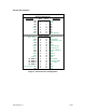
AL5721 Pin Function Description
Pin # Pin Name I/O Description
1 NC No Connection
2 3.3V +3.3V Regulated power from host system
3 NC No Connection
4 GND Ground connection
5 NC No Connection
6 NC No Connection
7 NC No Connection
8 NC No Connection
9 GND Ground connection
10 NC No Connection
11 NC No Connection
12 NC No Connection
13 NC No Connection
14 NC No Connection
15 GND Ground connection
16 USB VBUS I +5V USB Vbus Signal from host system
17 Host_Select I (1) High = True 3.3V CMOS signal, allows host
system to provide control of selection among
multiple hosts associated to UWB radio.
(2) Test function, holding Host_Select high at
+3.3V power application to the AL5721 and then
switching it low places the aL5721 into
Administrative Mode for control by Alereon
manufacturing test utility software
18 GND Ground connection
19 NC No Connection
20 W_Disable# I Low = True 3.3V CMOS signal, assertion of
W_Disable# completely disables the radio system.
21 GND Ground connection
22 Association_CLR I High = True 3.3V CMOS signal, assertion of
Association_CLR clears all stored host
associations
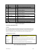
23 NC No Connection
24 NC No Connection
25 NC No Connection
26 GND Ground connection
27 GND Ground connection
28 Assoc. D+ I/O USB D+ of Association signal
29 GND Ground connection
30 Assoc. D- I/O USB D- of Association signal
31 NC No Connection
32 Assoc. VBUS I +5V USB Vbus Signal from association connector
33 NC No Connection
34 GND Ground connection
35 GND Ground connection