
User's Guide


UG-AL5721_1.0 P.3/7
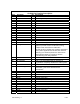
AL6621 Pin Function Description
Pin # Pin Name I/O Description
1 NC No Connection
2 3.3V +3.3V Regulated power from host system
3 NC No Connection
4 GND Ground connection
5 NC No Connection
6 NC No Connection
7 NC No Connection
8 NC No Connection
9 GND Ground connection
10 NC No Connection
11 NC No Connection
12 NC No Connection
13 NC No Connection
14 NC No Connection
15 GND Ground connection
16 USB VBUS I +5V USB Vbus Signal from host system
17 Host_Select# I (1) Low = True 3.3V CMOS signal, allows host
system to provide control of selection among
multiple hosts associated to UWB radio.
(2) Test function, holding Host_Select# asserted at
+3.3V power application to the AL5721 and then
switching it un-asserted places the aL5721 into
Administrative Mode for control by Alereon
manufacturing test utility software
18 GND Ground connection
19 NC No Connection
20 W_Disable# I Low = True 3.3V CMOS signal, assertion of
W_Disable# completely disables the radio system.
21 GND Ground connection
22 Association_CLR# I Low = True 3.3V CMOS signal, assertion of
Association_CLR clears all stored host
associations
23 NC No Connection
24 NC No Connection
25 NC No Connection
26 GND Ground connection
27 GND Ground connection
28 Assoc. D+ I/O USB D+ of Association signal
29 GND Ground connection
30 Assoc. D- I/O USB D- of Association signal
31 NC No Connection
32 Assoc. VBUS I +3.3V USB Vbus Signal from association connector
33 NC No Connection
34 GND Ground connection
35 GND Ground connection