ALESIS RMD REMOTE METER DISPLAY FOR THE M20 PROFESSIONAL 20-BIT DIGITAL RECORDING SYSTEM OWNER’S MANUAL FIRST EDITION VERSION 1.00 APPLIES TO M20 OPERATING SOFTWARE VERSION 1.
RMD, Appendix R RMD MANUAL 1.
APPENDIX R RMD REMOTE METER DISPLAY This document covers only those aspects unique to the RMD and should be inserted into the binder with the M20 manual. The RMD is a remote meter display designed exclusively for the ADAT-M20. It provides 32 channels of peak metering for up to four M20s. It will duplicate the meter ballistics of each M20’s front panel meter display settings. In addition, the RMD has eight front panel LEDs that provide fundamental feedback of each connected M20’s error status.
RMD, Appendix R IMPORTANT SAFETY INSTRUCTIONS AND COMPLIANCE NOTICES SAFETY SYMBOLS USED IN THIS PRODUCT This symbol alerts the user that there are important operating and maintenance instructions in the literature accompanying this unit. This symbol warns the user of uninsulated voltage within the unit that can cause dangerous electric shocks. All safety warnings in the M20 manual (pages v and vi) apply to the RMD as well and are incorporated herein by reference.
Appendix R, RMD INDUSTRY CANADA (DIGITAL APPARATUS) INTERFERENCE-CAUSING EQUIPMENT STANDARD ICES-003 ISSUE 2 This Class A digital apparatus meets all requirements of the Canadian InterferenceCausing Equipment Regulations.
RMD, Appendix R July, 1998 CONNECTING THE RMD TO THE M20 SYSTEM POWER The RMD works with any AC voltage from 90 to 250 volts, 50 to 60 Hz. This eliminates the need for transformers or voltage switches. The RMD ships with an IEC-spec power cord for the country to which the RMD was shipped. The RMD’s IEC-spec AC cord is designed for connection to an outlet that includes three pins, with the third pin connected to ground. Do not substitute a non-grounded AC cord or lift the ground.
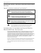
Appendix R, RMD 1. Connect one end of a control cable to the REMOTE connector on the CADI, and connect the other end to the connector labeled “CADI” on the RMD. Communication between the CADI and the M20(s) happens via the RMD connection to the first (ID 1/Master) M20 using the MACHINE 1 connector. Do not connect the first machine directly to the CADI when the RMD is in use. M20 CADI M20 M20 M20 RMD MANUAL 1.
RMD, Appendix R RMD OPERATION POWER-UP The RMD does not have to be powered up in any order with respect to the M20(s) or the CADI for it to work properly. The power switch is located on the left side of the RMD’s back panel. When the RMD is powered up, the track number indicators at the bottom of each meter will light with the appropriate track number (tracks 1-32). If M20s are connected, the Record and Input Enable status of each M20 will be reflected in the RMD’s display at power-up.
Appendix R, RMD “B” Indicator (Red LED) When a transport or system error occurs, the B indicator for the erring machine will flash until reset by pressing the Peak Clear button on either the CADI or the front panel of the offending M20. If a “B” indicator lights, immediately look at the display of the M20 itself for an error message. Write down the error code and refer to Alesis Product Support for more information. Some less serious M20 system error messages are displayed momentarily.