2-Way Wireless Security Suite v1.0 Installation Guide Models: PC9155-433/868 PC9155G-433/868 PC9155D-433/868 Used with: WT5500-433/868 WT5500P-433/868 TELEPERMIT These DSC Security Alarm Systems may be connected to the Telecom Network PTC 211 / 09 /017 PTC 211 / 09 /018 PTC 211 / 09 /019 PC9155-433 PC9155D-433 PC9155G-433 RN = 0.
SAFETY INSTRUCTIONS FOR SERVICE PERSONNEL WARNING: WHEN USING EQUIPMENT CONNECTED TO THE TELEPHONE NETWORK, THERE ARE BASIC SAFETY INSTRUCTIONS THAT SHOULD ALWAYS BE FOLLOWED. REFER TO THE SAFETY INSTRUCTIONS PROVIDED WITH THIS PRODUCT; SAVE THEM FOR FUTURE REFERENCE. INSTRUCT THE END-USER REGARDING THE SAFETY PRECAUTIONS THAT SHALL BE OBSERVED WHEN OPERATING THIS EQUIPMENT.
Guidelines for Locating Smoke & CO Detectors The following information is for general guidance only and it is recommended that local fire codes and regulations be consulted when locating and installing smoke alarms and CO Alarms. Smoke Detectors Research indicates that all hostile fires in homes generate smoke to a greater or lesser extent. Detectable quantities of smoke precede detectable levels of heat in most cases.
Limited Warranty Digital Security Controls warrants the original purchaser that for a period of twelve months from the date of purchase, the product shall be free of defects in materials and workmanship under normal use. During the warranty period, Digital Security Controls shall, at its option, repair or replace any defective product upon return of the product to its factory, at no charge for labour and materials.
Table of Contents Chapter Description Page 1. Introduction . . . . . . . . . . . . . . . . . . . . . . . . . . . . . . . . . . . . . . . . . . . . . . . . . . . . . . . . . . .1-1 2. Installation . . . . . . . . . . . . . . . . . . . . . . . . . . . . . . . . . . . . . . . . . . . . . . . . . . . . . . . . . . . .2-1 3. Operation . . . . . . . . . . . . . . . . . . . . . . . . . . . . . . . . . . . . . . . . . . . . . . . . . . . . . . . . . . . . .3-1 4. Programming . . . . . . . . . . . . . . .
PC9155 Wireless Alarm System 1 Introduction This manual provides installation and programming information for the PC9155 two-way wireless series of alarm panels. The PC9155 is a twoway wireless alarm system that can interface with one-way and two-way RF devices. Three separate hardware platforms exist for the 433 MHz and 868 MHz versions. 1.1 PC9155 Model Differences Models with a ‘G’ in the suffix have a GS2065 module installed.
1 Introduction 1.3 Controls & Indicators The PC9155 can have a maximum of eight status indicators located on the front panel. The four indicators located on the left side of the panel indicate the Ready status, Armed status, Trouble status and AC Power status of the alarm system. The four indicators are located on the right side of the panel only if a GS2065 or TL265GS module is installed. These indicate Communicator Trouble status, Network status (TL265GS only), and High or Low signal strength.
PC9155 Wireless Alarm System Entering Letters Some commands require the entry of letters (i.e., A, B, C, D, E, F). To enter a letter, press , and the number on the keypad that corresponds to the appropriate letter, as indicated below. 1=A 2=B 3=C 4=D 5=E 6=F The cursor will blink to indicate that you are entering letters. To revert back to numeric entry press , .
2 Installation 2 Installation 2.1 Hardware Installation Hardware Installation Step 1 Step 2 Select a suitable location for the alarm panel in a dry location, close to an unswitched AC outlet, phone line (if required), and Ethernet cable (if required). DO NOT mount system on an electrical box. Position system away from metal objects (e.g., appliances, furnace, duct work etc.). Gently pry the front cover from the chassis using a small slotted screwdriver in the slots provided.
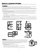
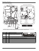
PC9155 Wireless Alarm System Figure 2-3 Mounting & Wiring Details %$&. 9,(: )5217 9,(: &29(5 5(029(' FUSE Internal Transformer Version Only Internal Transformer Version Only 3& /,1.
2 Installation 2.2 Wiring 1. I/O Wiring The two I/O terminals can be programmed as hard-wired zone inputs and/or PGM outputs. See programming section [013] Opt [1,2]. 1a. Zone Wiring Zones 1 - 32 are reserved for wireless zones. If programmed as zone inputs, I/O1 is zone 33 and I/O-2 is zone 34. Zones can be wired for Normally Open (NO) contacts with single-end-of-line resistors or Normally Closed (NC) contacts with single-end-of-line or doubleend-of-line resistors. Observe the following guidelines.
PC9155 Wireless Alarm System 1c. PC5950 2-Way Audio Verification Module Wiring 7DON /LVWHQ ZLWK 6LUHQ 6KXWGRZQ 3& • Install the PC5950 in a metal cabinet secured to a wall. • Power down the PC9155 if required. • Route wiring to the PC9155 through the wiring guide. • Route wiring to the audio stations as indicated (2 Max). • Ensure telephone line wiring enables the PC9155 to seize the line. • Test System. Refer to the PC5950 Installation Guide.
2 Installation Enroll wireless devices in the following sequence: • Keypad • Sirens • Sensors • Pendants • Wireless Keys Refer to the associated installation sheet for additional details on how to activate specific wireless devices. Enrolling Wireless Keypads When the PC9155 is first powered up a 2 minute window is established for enrolling the first keypad. The AC Power and Ready LEDs will flash for the duration of the enrollment window. The keypad must be powered up and enrolled within this period.
PC9155 Wireless Alarm System Enrolling Sensors & Pendants Step 1 Enter [*][8][5555][898] “Wireless Enrollment Mode” is displayed. Step 2 • Place the Wireless device near the alarm system. • Activate the device as described in the associated installation sheet. • The Electronic Serial Number (ESN) is displayed. • Press , to confirm serial number. Wireless Enrollment Mode 223E02 Confirm ESN? * The ESN is a 6-digit alphanumeric number located on a removable sticker on the wireless device.
2 Installation 2.4 Global Wireless Device Placement Test Wireless Device Placement Perform the Wireless Device Placement testing on keypads, sounders and sensors only. • This test is NOT required for wireless keys or pendants. Verify that pendants and Key FOBs operate within the desired operating area by arming and disarming the sytem. • Test each device multiple times to ensure a good placement. • If a device tests BAD reposition the device and retest.
PC9155 Wireless Alarm System Step 2 Enter a 2 digit zone number, keypad number, or siren number depending on the placement test section entered, or scroll to the desired device and press , to begin individual placement test. Step 3 Place the wireless device in the intended mounting location. Activate the device as described in the associated installation sheet. • If the alarm system receives a STRONG signal the bell will sound once and ‘Location is Good’ will be displayed on the LCD.
3 Operation 3 Operation 3.1 Operating Modes 3.1.1 – Away Arming Away Arming arms the entire system including the perimeter and interior devices. The Ready light must be ON to arm the system. If the Ready light is OFF, ensure all protected doors and windows are secure or bypassed. To arm the system in the Away mode, either press and hold the Away function key for 2 seconds or enter a valid user code and leave the premises through a door programmed as Delay.
PC9155 Wireless Alarm System [ ][1] – Bypass/Re-activate Stay/Away and Night Zones Press [ ][1] to enter Bypass mode. If the Code Required for Bypass option is enabled, enter a valid user code. The keypad displays ‘Scroll to Bypass Zones’. The keypad displays the programmed zone labels and includes the letter ‘O’ in the bottom, right corner if the zone is violated or the letter ‘B’ if the zone is bypassed.
3 Operation [1] Supervisor’s Code: This attribute is used for validation when entering the [ ][5] User Code Programming section and [ ][6] User Functions section. Note, the supervisor’s code can only validate programming for codes with equal or lesser attributes. The supervisor’s code also allows this user to create bypass groups if an access code is required to enter into [ ][1] Bypassing.
PC9155 Wireless Alarm System [ ][7][1 or 2] – Command Outputs (1&2) Press [ ][7] then [1] or [2]. If the Command Output Code Required option is enabled, enter a valid user code. The panel activates a command output assigned to any PGM. [ ][8] – Installer Programming Press [ ][8][Installer Code] to enter Installer Programming. Installer programming allows the installer to program all system functions. Refer to the section 5: Installer Programming for details.
4 Programming 4 Programming The PC9155 can be programmed using three methods: • Template Programming - Allows the minimum required data to be programmed. It also allows for the setup of DLS downloading software. • DLS Programming - Allows programming to be downloaded using DLS-IV®™ software. - DLS programming can be performed locally with a PC-Link cable and a PC with DLS-IV software installed. - DLS programming can be performed remotely via telephone line, GPRS network or the Internet.
PC9155 Wireless Alarm System Step 2 Once in the programming section, the 4-digit number “0111” is displayed. Enter to accept the existing default programming. See the tables below for details of Digit 1, 2, 3 and 4. Step 3 After entering ‘0001’, the first telephone entry is displayed. Enter the monitoring station telephone number after the “D”. Do NOT delete any of the remaining “Fs” E.g., To enter 02-1234-5678: Press followed by to complete the entry. See section [301] for additional details.
4 Programming • Digit 2 selects one of the following reporting code options: Opt# Phone Line 1 Programming Section Phone Line 3 Programming Section 0 This entry will not change the existing communications programming.
PC9155 Wireless Alarm System Digit 4 indicates/selects one of the following DLS connections: Option Double Call Call Back Sect [401] Opt 1 Sect [401] Opt 3 User Call Up Sect [401] Opt 4 #Rings Sect [406] 1 000 2 008 3 008 4 008 4.2 DLS Programming 4.2.1 Local Programming with PC-Link Follow the steps below in the sequence indicated. Step 1 Ensure front cover is removed and the system is powered up. i PC-Link connections are ‘hot-swappable’.
5 Installer Programming 5 Installer Programming 5.
PC9155 Wireless Alarm System 5.
5 Installer Programming [ 006] Ins taller's Code i D ef [ 007] Mas t er Code [008] Maintenanc e Code T hes e c odes ar e 4 or 6- digits ( pr ogr ammed in s ec tion[701] O pt [5]) .
PC9155 Wireless Alarm System [ 015] Third S y s t em Opt ions O pt 1 2 3 4 5 6 7 8 N A C P EU 9 9 9 9 9 9 9 9 9 9 9 9 ON [F] Key Enabled [P] Key Audible (Siren / Beeps) Quick Exit Enabled Quick Arming Enabled (*0 And Function Keys) Code Required For Bypassing Master Code Not Changeable TLM Enabled System Tamper Enabled OFF [F] Key Disabled [P] Key Silent Quick Exit Disabled Quick Arming Disabled (Funct. Keys Req.
5 Installer Programming [ 101] -[ 134] Zone A t t ribut es (A t t ribut es 10-13 are res erv ed f or Fut ure Us e) Attri b u te : Zo n e Typ e 00 Null Zone 01 Delay 1 02 Delay 2 03 Instant 04 Interior 05 Interior Stay/Away 06 Delay Stay/Away 07 Future Use 08 Future Use 09 24-Hour Supervisory (Hardwired) 10 24-Hour Supervisory Buzzer 11 24-Hour Burglary 12 Future Use 13 24-Hour Gas 14 Future Use 15 24-Hour Medical 16 24-Hour Panic 17 24-Hour Emergency 18 Future Use 19 24-Hour Water 20 24-Hour Freeze 21 Futur
PC9155 Wireless Alarm System [ 167] GP RS / E t hernet Int erf ac e Com m unic at ions Wait For A c k Valid Entries 001-255 seconds N A 020 C P 020 EU 020 [ 168] S et Cloc k Forward (Day light S av ing) [ 169] S et Cloc k B ac k (S t andard Tim e) N A C P EU Month Week N A C P EU 003 003 003 Valid Entries 001-012 Month 011 011 010 Valid Entries 001-012 002 002 005 Valid Entries 001-005 Week 001 001 005 Valid Entries 001-005 Day 000 000 000 Valid Entries 000-031 Day 000 000 000 Valid En
5 Installer Programming Reporting Codes i All Repor ting Codes ar e defaulted ‘F F ’ unles s indic ated other wis e.
PC9155 Wireless Alarm System [3 3 0 ]-[3 3 2 ] Ta m p e r R e p o rti n g C o d e s Se cti o n [ 330] [ 331] [ 332] Zone 1 Zone 2 Zone 3 Zone 4 Zone 5 Zone 6 Zone 7 Zone 8 Zone 9 Zone 10 Zone 11 Zone 12 Zone13 Zone 14 Zone 15 Zone 16 Zone 17 Zone 18 Zone 19 Zone 20 Zone 21 Zone 22 Zone 23 Zone 24 Zone 25 Zone 26 Zone 27 Zone 28 Zone 29 Zone 30 Zone 31 Zone 32 Zone 33 Zone 34 [3 3 4 ]-[3 3 6 ] Ta m p e r R e sto ra l R e p o rti n g C o d e s Se cti o n [ 334] [ 335]
5 Installer Programming [3 4 2 ] Op e n i n g (D i sa rm i n g ) R e p o rti n g C o d e s- Acce ss C o d e s 1 -1 6 Code 1 Code 2 Code 3 Code 4 Code 5 Code 6 Code 7 Code 8 Code 9 Code 10 Code 11 Code 12 Code 13 Code 14 Code 15 Code 16 [3 4 4 ] Mi sce l l a n e o u s Op e n i n g (D i sa rm i n g ) R e p o rti n g C o d e s Opening By Access Code 40 Special Opening Late To Open [3 4 5 ] Ma i n te n a n ce Al a rm R e p o rti n g C o d e s Battery Trouble Alarm AC Failure Trouble Alarm For F
PC9155 Wireless Alarm System [3 4 8 ] Te st Tra n sm i ssi o n R e p o rti n g C o d e s Walk Test End Walk Test Begin For Future Use Periodic Test Transmission System Test [ 350] Com m unic at or Form at Opt ions 1st Telephone Number NA 04 C P 04 EU 04 2nd Telephone Number NA 3rd Telephone Number 04 C P 04 EU 04 4th Telephone Number 04 C P 04 EU 04 NA NA 04 C P 04 EU 04 01 20 BPS, 1400 Hz 02 20 BPS, 2300 Hz 03 DTMF Contact ID 05 Future Use * 06 Residential Dial * Failure to communicate using Res
5 Installer Programming [ 378] Tes t Trans m is s ion Tim e of Day D ef 9999 Valid entries are (0000-2359), 9999 to disable [ 380] Firs t Com m unic at or Opt ions O pt 1 2 3 4 5 6 7 8 N A C P EU 9 9 9 ON Communications Enabled Restores On Siren Time-Out Pulse Dialing For Future Use For Future Use Alternating Backup Dial For Future Use Delinquency Follows Zone Activity (Hours) OFF Communications Disabled Restores Follow Zones DTMF Dialing Call Primary Number, Backup To Secondary Delinquency Follows
PC9155 Wireless Alarm System [ 401] Firs t Downloading Opt ions O pt 1 2 3 4 5 6 7 8 N A C P EU 9 9 9 ON Answering Machine / Double Call Enabled User Enable DLS Call-Back Enabled User Initiated Call-Up Enabled For Future Use Call Up is 300 Baud For Future Use For Future Use OFF Answ.
5 Installer Programming * Attributes for Option 9 & 10 Attri b u te : ON OFF 09 S y s t em Trouble Event Disabled Attri b u te : S ec t P GM [ 501] [ 502] 1 2 4 3 5 AC Fail TLM Fault Device Fault FTC Disabled Disabled Disabled Disabled 6 Device 7 Device 8 Loss of Tamper Disabled Low Disabled Clock Disabled 9 9 9 9 9 9 9 9 1 2 Fire 3 Panic 4 Medical 5 Supervisory 6 Priority 7 Duress 8 Follows Event Disabled Event Disabled Event Disabled Event Disabled Event Disabled E
PC9155 Wireless Alarm System [ 701] Firs t Int ernat ional Opt ions O pt ON 50 Hz AC Input Time Base is Internal Crystal AC/DC Arming Inhibit Enabled All System Tampers Require Installer Reset 6-Digit User Access Codes Busy Tone Detection Enabled For Future Use For Future Use N A C P EU 1 2 3 4 5 6 7 8 9 OFF 60 Hz AC Input Time Base is AC Line AC/DC Arming Inhibit Disabled All System Tampers Follow Restore 4-Digit User Access Codes Busy Tone Detection Disabled [ 702] S ec ond Int ernat ional Opt ions
5 Installer Programming [804] [ 001] -[ 032] Wireles s Dev ic e Serial Numbers Zone Sub Sec t . 1 [001] Serial Number Zone Sub Sec t. 12 [012] Zone Sub Sec t.
PC9155 Wireless Alarm System Sub Sec t. Sub Serial Number Sec t. Sub #1 Sec t. D ef 03 [109] [149] [182] 9 10 [110] [150] 9 11 [111] [151] 9 12 [112] [152] 9 13 [113] [153] 9 14 [114] [154] 9 15 [115] [155] 9 16 [116] [156] 9 9 #2 04 D ef #3 27 D ef #4 30 D ef #5 D ef 13 #6 14 D ef D ef Refer to section [804][141]-[156] in the Programming Descriptions section of this guide and in the wireless key installation sheet.
5 Installer Programming [ 804] [ 314] Wireles s S iren #04 Opt ions O pt 1 2 3 4 5 6 7 8 N A C P EU 9 9 9 9 9 9 9 9 9 9 9 9 ON Siren Alarm Enabled Buzzer Notifications Enabled Door Chime Enabled Trouble Beeps Enabled Squawks Enabled Enable Strobe Buzzer Alarm / Strobe Follows BTO Siren Tamper Enabled OFF Siren Alarm Disabled Buzzer Notifications Disabled Door Chime Disabled Trouble Beeps Disabled Squawks Disabled Disable Strobe Buzzer Alarm / Strobe Follows Alarm Condition Siren Tamper Disabled [ 804
PC9155 Wireless Alarm System O pt N A C P EU 1 2 3 *4 5 6 7 8 9 9 9 9 9 9 ON Ethernet Receiver #1 Supervised GPRS Receiver #1 Supervised Commercial Supervision GPRS Primary Redundant Communications Enabled Remote Firmware Upgrade Enabled For Future Use For Future Use OFF Ethernet Receiver #1 Not Supervised GPRS Receiver #1 Not Supervised Residential Supervison Ethernet Primary Redundant Communications Disabled Remote Firmware Upgrade Disabled * Default O N Applies to G S2065 Models O nly [ 851] [ 011]
5 Installer Programming D ef OBF5 / 3061 OBF9 / 3065 D ef Valid Port Entries are 0000-FFFF (0-65535) [ 851] [ 124] Et hernet Tes t Trans mis s ion Time D ef 9999 Valid Entries are 0000-2359, 9999 to disable [ 851] [ 125] Et hernet Tes t Trans mis s ion Cy c le D ef DDHHMM 000000 [ 851] [ 203] GPRS Rec eiv er#1 IP Addres s D ef 0.0.0.
PC9155 Wireless Alarm System [ 851] [ 225] GP RS Tes t Trans mis s ion Cy c le D ef DDHHMM 000000 [ 851] [ 991] Firmware V ers ion D ef 01.00.01.TT • • • [ 851] [ 992] E t hernet IP A ddres s D ef 0.0.0.0 • • • [ 851] [ 993] E t hernet Gat eway IP A ddres s D ef 0.0.0.0 • • • • • [ 851] [ 994] GP RS IP A ddres s D ef 0.0.0.
5 Installer Programming [ 996] Res t ore 9155 Wireles s Dev ic e P rogramming Fac t ory Def ault s Enter [996][Installer Code][996] [ 998] Res t ore 9155 P anel Only ) Fac t ory Def ault Enter [998][Installer Code][998] [ 999] S y s t em Def ault Enter [999][Installer Code][999] See Chapter 6.
PC9155 Wireless Alarm System [ 001] -[ 034] Label P rogramming (Zone 01-34) c ont inued 17 [017] 26 [026] 18 [018] 27 [027] 19 [019] 28 [028] 20 [020] 29 [029] 21 [021] 30 [030] 22 [022] 31 [031] 23 [023] 32 [032] 24 [024] 33 [033] 25 [025] 34 [034] [ 065] Fire A larm Label (2 x 14 Charac t ers ) F I R E — Z O N E ————— —————————————— Def [ 066] Fail To A rm E v ent Mes s age (2 x 16 Charac t ers ) S Y S T E M — H A S —————— F A I L E D — T O — A R M ——— Def [ 067] A
5 Installer Programming [ 075] S ec ond K ey pad Opt ions O pt N A C P EU 1 2 3 4 5 6 7 8 9 9 9 9 9 9 9 9 9 9 9 9 9 9 9 ON Local Clock Display Enabled Local Clock Displays 24 Hr Time Auto Alarm Scroll Enabled Language Selection Available From Any Menu Power LED Enabled Power LED Indicates AC Present Alarms Are Displayed While Armed Auto Scroll Open Zones Enabled OFF Local Clock Display Disabled Local Clock Displays AM/PM Auto Alarm Scroll Disabled Language Selection Available From Installer's Only Powe
PC9155 Wireless Alarm System 5.3 Programming Descriptions This section describes all of the PC9155 programming options. [001]-[002] Zone Definitions Each of these sections requires a 2-digit entry to determine how a zone functions. Refer to sections [132] to [134] for zone attribute programming. Zone Types i 00 01 Null Zone: This zone type is intended for zones that are NOT used.
5.3 Programming Descriptions i 24 25 This zone type must NOT be used for wireless zones. Activation of a keyswitch zone is intended to arm or disarm the system. Activation of the zone will not log or transmit the Police code. A bypass on this zone type will not be un-bypassed when the system is disarmed. When the zone is bypassed, a zone bypass event buffer log and communication occurs immediately, NOT when the system is armed.
PC9155 Wireless Alarm System [005] System Timers This section has two subsections. Entry/Exit delays are in subsection 01and Bell Cut-off is in subsection 09. Subsections 02-08 are reserved for future use. Enter the corresponding 2-digit entry to access these subsections. [01] Entry Delay 1: (001-255) seconds This value determines the entry delay time for delay 1 type zones. Entry Delay 2: (001-255) seconds This value determines the entry delay time for delay 2 type zones.
5.3 Programming Descriptions • 24 hour supervisory buzzer zone alarm • No activity arm pre-alert • Entry delay • Audible exit fault • Audible exit delay • Door chime This PGM type does not activate for local key presses or trouble beeps. 08 Courtesy Pulse. This PGM output switches to ground for 2 minutes past the end of entry or exit times to allow enough time for complete entry to or exit from the premises. If the system is armed through the No Activity Arming method this output will NOT activate.
PC9155 Wireless Alarm System [013] First System Options Option [1] Description ON: Zone 33/PGM 1 Selection: Hardwired Zone 33 Input is enabled. The I/O-1 terminal functions as an input for Zone 33. The zone definition is programmed in the first entry of section [009]. Zone supervision is determined by attributes 14, 15, and 16 programmed in sections [133]. OFF: PGM 1 Output Enabled: The I/O-1 terminal functions as an output. The PGM type is programmed in the first entry of section [009].
5.3 Programming Descriptions [2] ON: Panic Key Audible. When a valid Panic key alarm is generated, the keypad buzzer sounds a series of 3 beeps to acknowledge the alarm. The buzzer then sounds a steady tone for the length of the bell time-out or until an access code is entered. OFF: Panic Key Silent. When a valid Panic key alarm is generated, the keypad buzzer and the bell output remain silent, but the alarm is still transmitted (if programmed). [3] ON: Quick Exit Enabled. See [ ][0] in section 3.
PC9155 Wireless Alarm System [018] Sixth System Options Option [1] [2] Description For Future use ON: Keypad Tamper Enabled. All system keypads will generate tamper troubles and restorals. OFF: Keypad Tampers are disabled. System keypads will NOT generate tamper troubles and restorals. [3]-[4] [5] For Future use ON: Keypad Buzzer Follows Bell Enabled. The keypad buzzers follow the bell status. OFF: Keypad Buzzer Follows Bell Disabled. The keypad buzzers do NOT follow all bell activity.
5.3 Programming Descriptions [030] Zone Loop Response Option [1] Description ON: Zone 33 is Fast Loop Response: Zone 33 has a fast loop response (36 ms). OFF: Zone 33 is Normal Loop Response: Zone 33 has a normal loop response (400 ms). [2] ON: Zone 34 is Fast Loop Response: Zone 34 has fast loop response (36 ms). OFF: Zone 34 is Normal Loop Response: Zone 34 has normal loop response (400 ms).
PC9155 Wireless Alarm System [167] GPRS/Ethernet Interface Communications Wait for ACK This value represents the time the communicator waits for an acknowledgement (ACK) from the receiver after sending the SIA packet to the central station. [168]-[169] Daylight Saving Time These sections provide support for programming the beginning and the ending of daylight-saving time.
5.3 Programming Descriptions [301] First Telephone Number The information in this section also applies to sections [302], [303] and [305]. These sections determine which type of communicator is activated in the event of an alarm (telephone, GPRS and Ethernet) and the sequence that the system follows in the event of an unsuccessful communication. • Entry of [D] followed by a [Telephone Number] terminated with ‘F’ configures the section for telephone dialing. E.g.
PC9155 Wireless Alarm System [328] Miscellaneous Alarm Reporting Codes Duress Alarm This reporting code is transmitted whenever a Duress code is used to perform any function on the system. The reporting code is sent to the Alarm & Restore call direction group. Opening After Alarm This reporting code is transmitted when the system is disarmed after an alarm; if an alarm occurred during the previous armed period. The reporting code is sent to the Alarm & Restore call direction group.
5.3 Programming Descriptions Exit Fault If an Exit Error occurs and entry delay expires before the system is disarmed, this reporting code is sent. This reporting code is sent to the Openings & Closings call direction group . i If the delay zone that caused the exit error has cross zoning enabled, the exit fault and zone alarm will still transmit if a second zone is not violated. This is to inform the central station that the premise is not secure. The local alarm sequence follows the cross zoning rules.
PC9155 Wireless Alarm System General Zone Fault & Restore This reporting code is sent whenever a zone has entered the fault state. This occurs when there is a short on DEOL hardwired zones and/or a loss of supervisory on a wireless zone. These reporting codes are sent to the System Maintenance call direction group. Delinquency The Delinquency Reporting code is transmitted in one of two ways.
5.3 Programming Descriptions Swinger Shutdown (Maintenance Troubles & Restores) This value determines the number of times the same system Maintenance (Trouble) type event will occur before stopping transmissions. Fire Troubles follow the Maintenance Swinger Shutdown variable. Program a 3-digit number from 000 to 014. When programmed with 000, Swinger Shutdown is disabled and all maintenance troubles are transmitted.
PC9155 Wireless Alarm System i [7] [8] If all 5 attempts to the designated phone numbers fail, an FTC trouble for the primary phone number is initiated and logged to the event buffer regardless of how this option is configured. For Future Use ON: Delinquency Follows Zone Activity (Activity Delinquency). If there is no zone activity, the Delinquency Transmission Delay timer in section [377] begins counting in hours.
5.3 Programming Descriptions [6] ON: AC Failure Communication Delay in Hours. The System AC Failure Communication Delay in section [377] is programmed in hours. OFF: AC Failure Communication Delay in Minutes. The System AC Failure Communication Delay in section [377] is programmed in minutes. [7] ON: Number of Dialing Attempts for Residential Dial Communication Format. Number of dialing attempts is 1 when using the Residential Dial Communication format.
PC9155 Wireless Alarm System OFF: Call-Back Disabled. The downloading computer has immediate access to the panel if it is identified as a valid downloading computer. ON: User Call-Up Enabled. When this feature is enabled, the user may initiate a single call attempt to the downloading telephone number by entering [ ][6][Master Code][6]. OFF: User Call-Up Disabled. An error tone is generated when [ ][6][Master Code][6] is entered. For Future Use ON: 300 Baud Panel Call-Up.
5.3 Programming Descriptions The following attributes are available for the System Trouble PGM option [09] System Trouble PGM (Type 09) [1] Service Required [2] A.C.
PC9155 Wireless Alarm System [701] First International Options Code Option [1] Description ON: 50 Hz AC. The incoming AC power cycles at 50 Hz. OFF: 60 Hz AC. The incoming AC power cycles at 60 Hz. [2] ON: The time base is the internal crystal oscillator. The internal crystal is used for the time base instead of AC power. OFF: The time base is the AC power input. The 50 or 60 Hz AC power is used for the time base. [3] ON: AC/DC Arming Inhibit with Battery Check Enabled.
5.3 Programming Descriptions Option [1] Description ON: Standard Door Chime Enabled. Traditional door chime tone found on other DSC keypads (6 quick beeps) OFF: Standard Door Chime Disabled [2] ON: ‘Bing-Bong’ Door Chime Enabled OFF: ‘Bing-Bong’ Door Chime Disabled [3] ON: ‘Ding-Dong’ Door Chime Enabled. OFF: ‘Ding-Dong’ Chime Disabled. [4] ON: 4-second Alarm Tone Door Chime Enabled. The keypad/siren will sound a medium volume alarm signal for 4 seconds. OFF: 4-second Alarm Tone Door Chime Disabled.
PC9155 Wireless Alarm System [ ][9] No-Entry Arm [ ][4] Chime On / Off Command Output 1 [ ][7][1] Command Output 2 [ ][7][2] [ ][0] Quick Exit [ ][1] Reactivate Stay/Away Zones Instant Stay Arm Disarm (Off) Auxiliary Alarm Panic Alarm Night Arm 05 06 13 14 16 17 25 27 29 30 33 [ ][9] No-Entry Arm can be used if the wireless key being used is identified. YES [ ][7][1] commands can be used with an access code if the wireless keys are identified.
5.3 Programming Descriptions [2] ON: Pre-Alarm Signal Enabled. When the system begins entry delay the entry delay time is sent to the wireless siren. If the wireless siren does not receive a disarm command during the entry delay time, the siren will go into alarm. OFF: Pre-Alarm Signal Disabled. When the system begins entry delay no entry delay time is sent to the wireless siren. The siren will not go into alarm until it receives a signal from the panel to tell it to go into alarm.
PC9155 Wireless Alarm System [999] Restore Factory Default Programming All programming, including wireless device programming, returns to the factory defaults. [ ] Keypad Programming To enter Keypad Programming press [ ][8][Installer Code][ ]. Keypad sections require 3-digit entries and only affect the keypad used to program them. [000] Local Keypad Function Key Programming This section is accessed by entering [ ][000] from Installer Programming. This section is used to program the keypad function keys.
5.3 Programming Descriptions [001]-[069], [100]-[125] Label Programming Zone and other labels in these sections can be customized. Default labels are in English and do not change when an alternate language is selected. Labels can be programmed locally or downloaded/uploaded using DLS and Connect 24 interactive software. Press 1. Enter the section number of the desired label to be programmed. 2. 3. Scroll to the desired character’s location using the <> Keys.
PC9155 Wireless Alarm System [075] Second Keypad Options Option [1] [2] Description ON: Local Clock Enabled. When the keypad is idle, the date and time are displayed until a key is pressed. OFF: Local Clock Disabled. When the keypad is idle, the display shows current system status. ON: Local Clock Displays 24 Hr Time. The local clock displays time in 24hr format (i.e., 00:00 - 23:59). OFF: Local Clock displays AM/PM Time. The local clock displays time in 12hr format (i.e., 12:00 AM - 12:00 PM).
5.3 Programming Descriptions [998] Initiate Global Label Broadcast Programmed keypad labels are broadcast and installed on all system keypads from keypad 1. Enter [ ][998] to broadcast the labels programmed in sections [ ][001]-[069] and [ ][100]-[125]. This function is also required for broadcasting labels downloaded using DLS software. i This function can only be initialized from keypad 1. All labels should be manually programed on the first keypad enrolled on the system in order to broadcast.
PC9155 Wireless Alarm Panel 6 Testing & Troubleshooting 6.1 Wireless Device Placement Test See sections 2.4 and 2.5 6.2 Testing the System Inform the monitoring station when beginning or ending alarm system testing. It is the user’s responsibility to test the alarm system weekly (excluding smoke detectors). Ensure that all the steps in the two tests below are followed.
6 Testing & Troubleshooting 6.3 Resetting the System to Factory Defaults Resetting the alarm system returns it to the factory programmed defaults. All programmed information including wireless enrollment, telephone numbers etc. will be lost. • The Installer code changes back to [5555]. • The Master code reverts back to [1234].
PC9155 Wireless Alarm Panel [ ][2] Troubles • • • Power up system Enter [ ][2] to view Troubles Perform actions indicated in the tables below [ ][2] Trouble Summary Trouble [0] GPRS/Ethernet Module Trouble Trouble [1] Service Required - Press [1] for more information Low Battery General System Trouble General System Tamper Trouble [2] AC Trouble Trouble [3] Telephone Line Trouble Trouble [4] Failure to Communicate Trouble [5] Device Fault - Press [5] for more information Trouble [6] Device Tamper - Press
6 Testing & Troubleshooting Trouble [2] AC Failure AC Failure No AC at panel AC input terminals. • Verify voltage measured across AC terminals is 16-18VAC. Replace transformer if required. Trouble [3] Telephone Line Trouble Telephone Line Trouble Phone line voltage at TIP, RING on main panel less than 3VDC. Measure the voltage across TIP and RING on the panel: • No phone off-hook – 50VDC (approx.). • Any phone off-hook – 5VDC (approx.). Wire incoming line directly to TIP and RING.
PC9155 Wireless Alarm Panel Trouble [7] Wireless Device Low Battery 1st press - Wireless Zones 2nd press - Wireless Keys 3rd press - Wireless Keypads 4th press - Wireless Sirens 5th press - Proximity Tags Press [7] to scroll through specific devices with a Low Battery Trouble One or more wireless devices has a low battery. NOTE: The event is not logged to the event buffer until the wireless device low battery delay time expires. Program section [377]. Replace Battery • Verify zone operation.
Appendix A: Reporting Code Formats Appendix A: Reporting Code Formats The following tables contain Contact ID and Automatic SIA format reporting codes. See programming sections [320]-[348] for reporting codes. Contact ID The first digit (in parentheses) is automatically sent by the control. The second two digits are programmed to indicate specific information about the signal. For example, if zone 1 is an entry/exit point, you could program the event code as [34].
PC9155 Wireless Alarm Panel S e c t io n # R e po rt ing C o de C o de S e nt Whe n D ia le r D ire c t io n A ut o m a t ic C o nt a c t ID C o de s S IA A ut o R e p C o de s M A /R R(3)A 2-000 YR-00 M A /R E(3)A 1-000 A T-00 [346] B attery Tro uble Resto re [345] A C Line Tro uble [346] A C Line Resto re P C9155 system battery vo ltage no rmal A C po wer to co ntro l panel is disco nnected o r interrupted (Fo llo ws A C Failure co mmunicatio n delay) A C po wer resto red (Fo llo ws A C
Appendix A: Reporting Code Formats S e c t io n # R e po rt ing C o de D ia le r D ire c t io n A ut o m a t ic C o nt a c t ID C o de s S IA A ut o R e p C o de s A wireless supervisio n fault has resto red fo r Keypad 2 M A /R R(3)8A -071 UJ-71 C o de S e nt Whe n [347] Keypad 2 Fault Resto re [347] Keypad 3 Fault A wireless supervisio n fault has o ccurred fo r Keypad 3 M A /R E(3)8A -072 UT-72 [347] Keypad 3 Fault Resto re A wireless supervisio n fault has resto red fo r Keypad 3 M
PC9155 Wireless Alarm Panel Contact ID Programmed Zone Alarm/Restoral Event Codes (as per SIA DCS: ‘Contact ID’ 01-1999): Program any of these codes for zone alarms/restorals when using the standard (non-automatic) Contact ID reporting format.
Appendix B: Communicator Format Options Appendix B: Communicator Format Options The following format options are programmable in section [350] 01 02 20 BPS, 1400 Hz handshake 20 BPS, 2300 Hz handshake • BPS Formats - 0 is not valid in Account or Rep Code (A must be used) Depending on the pulse format selected the panel will communicate using the following: 3/1, 3/2, 4/1 or 4/2, 1400 or 2300 Hz handshake, 20 bits per second, nonextended. The digit ‘0’ will send no pulses and is used as a filler.
PC9155 Wireless Alarm Panel Appendix C: 2-Way Audio Verification (PC5950) Not approved for use with UL/ULC listed installations. Audio Verification provides Talk and Listen-in capability for audio verification of alarms. This allows the central station to communicate with the occupants through the microphone and speaker of the alarm system. The commands indicated below are a subset of the SIA Audio Verification Standard (November 11, 1997). The 2-way Audio Session 1.
Appendix D: Regulatory Approvals Information Appendix D: Regulatory Approvals Information North America will provide advance notice in order for you to make necessary modifications to maintain uninterrupted service. FCC COMPLIANCE STATEMENT Equipment Maintenance Facility CAUTION: Changes or modifications not expressly approved by Digital Security Controls could void your authority to use this equipment.
PC9155 Wireless Alarm Panel This product has been tested and found in compliance with the following standards: UL1023 Household Burglar-Alarm System Units UL985 Household Fire Warning System Units UL1635 Digital Alarm Communicator System Units ULC-S545-02Residential Fire Warning System Control Units ORD-C1023-1974Household Burglar-Alarm System Units This product has also been tested and found in compliance with the ANSI/SIA CP-01-2007 Control Panel Standard – Features for False Alarm Reduction.
Appendix D: Regulatory Approvals Information SIA False Alarm Reduction Installations For a list of the defaults value programmed when the unit is shipped from the factory and for any other programming information refer to table below. Caution: Call Waiting Cancel (section [382], Option 4) feature on a non-Call Waiting line will prevent successful communication to the supervising station.
Europe This product is in conformity with: EMC Directive 2004/108/EC based on results using harmonized standards in accordance with article 10(5), R&TTE Directive 1999/5/EC based on following Annex III of the directive and LVD Directive 99/5/EC based on results using harmonized standards. The product is labeled with the CE mark as proof of compliance with the above mentioned European Directives. Also a CE declaration of conformity (DoC) for this product can be found at www.dsc.