DATA CENTER and CAMPUS NETWORKS Deploying Brocade Networks with Microsoft Lync Server 2010 This paper describes the best practices for configuring a Brocade network infrastructure with Microsoft Lync Server 2010, details the role of network layers in a data center, and explains why a solid network foundation is critical for a successful deployment.
DATA CENTER and CAMPUS NETWORKS DEPLOYMENT GUIDE CONTENTS Introduction..........................................................................................................................................................................................................................................4 A Global Workforce ..........................................................................................................................................................
DATA CENTER and CAMPUS NETWORKS DEPLOYMENT GUIDE Setting Up Active-Standby VIP Redundancy.........................................................................................................27 Setting Up Active-Active Redundancy ...................................................................................................................27 Configuring PoE for the Campus Network ................................................................................................................
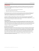
DATA CENTER and CAMPUS NETWORKS DEPLOYMENT GUIDE INTRODUCTION Workers today have many means of communication—cell phones, office phones, voice mail, Voice over IP (VoIP), fax, e-mail, instant messaging (IM), video conferencing, and other ways to communicate. Advances in each of these technologies has increased productivity and enabled instant contact with anyone across the globe. However, this poses some IT challenges: • Users still depend on their own isolated infrastructure and devices.
DATA CENTER and CAMPUS NETWORKS DEPLOYMENT GUIDE SOLUTION COMPONENTS The Network At the core of UC is the underlying network. With voice and video converging to the same network that transmits an organization’s data, demands rise exponentially. Successful deployment of Microsoft Lync Server 2010 requires a solid, open, and scalable network infrastructure.
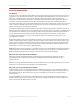
DATA CENTER and CAMPUS NETWORKS DEPLOYMENT GUIDE Figure 1. Microsoft Lync Server 2010 expanded deployment. Eight Front End Servers running the recommended hardware can support 100,000 active concurrent users per pool. The following considerations apply to the Enterprise Edition consolidated configuration: • A single Enterprise Edition server can be configured as an enterprise pool. • A hardware load balancer is required when two or more Enterprise Edition servers are configured as a pool.
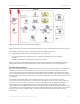
DATA CENTER and CAMPUS NETWORKS DEPLOYMENT GUIDE Figure 2. Survivable branch appliance overview. CALL ADMISSION CONTROL (CAC) For IP-based real-time applications such as IP telephony, video, and application sharing, enterprise network bandwidth is generally not considered a limiting factor in LAN environments. However, on WAN links between sites, bandwidth is a finite resource. Ultimately, provisioning these links adequately is the correct approach.
DATA CENTER and CAMPUS NETWORKS • DEPLOYMENT GUIDE Real-time metrics of the actual experience. Microsoft takes metrics to a new level and goes beyond monitoring network metrics such as packet loss, jitter, and latency. Microsoft monitors the QoE of all users on all calls by using Microsoft Lync Server 2010 Monitoring Server, which collects comprehensive metrics and aggregates them in a Call Detail Record (CDR).
DATA CENTER and CAMPUS NETWORKS DEPLOYMENT GUIDE • Processing delay includes the time required to collect a frame of voice samples before processing by the speech encoder can occur—the actual process of encoding, encrypting if appropriate, packetizing for transmission—and the corresponding reverse process on the receiving end, including the jitter buffer used to compensate for varying packet arriving delay on the receiving end.
DATA CENTER and CAMPUS NETWORKS DEPLOYMENT GUIDE Packet Loss Packet loss occurs when packets are sent but not received at the final destination, due to a network problem. Packet loss is the proportion (in percentages) of packets lost en route across the end-to-end network.
DATA CENTER and CAMPUS NETWORKS DEPLOYMENT GUIDE the Microsoft Lync Server 2010 environment if bandwidth is saturated. Fixed rate limiting allows you to specify the maximum number of bytes a given port can send or receive, and it applies to all traffic on the rate-limited port. REFERENCE ARCHITECTURE Unified Communications, particularly High Definition (HD) video, is a significant driver of network traffic.
DATA CENTER and CAMPUS NETWORKS DEPLOYMENT GUIDE Core Layer The core layer consists of high-speed, high-performance, and highly available switches, which connect the aggregation layers and—in smaller environments—the access layer. In many cases, redundant 10 GbE links connect the different layers, to provide the required bandwidth.
DATA CENTER and CAMPUS NETWORKS DEPLOYMENT GUIDE It is critical that you have reliable and deterministic switches that can quickly converge when outages occur. Outages are inevitable, but having a solid design and robust Brocade switches keeps your network up and running without affecting applications. Hardware Load Balancing Load balancing technology has become a technology of choice to improve the scalability, availability, and security of IP applications.
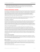
DATA CENTER and CAMPUS NETWORKS DEPLOYMENT GUIDE Figure 4. Lync reference architecture for campus environments. Core Layer The core layer consists of high-speed, high-performance, and highly available switches, which connect the aggregation layers and, in smaller environments, the access layer. In many cases, redundant 10 GbE links connect the different layers to provide the required bandwidth.
DATA CENTER and CAMPUS NETWORKS DEPLOYMENT GUIDE access layer includes devices such as workstations, VoIP phones, and notebooks, which do not typically require the same performance demands as servers require in the data center. However, the campus LAN access layer requires PoE and PoE+ for IP phones. In most cases 1 GbE is sufficient to meet most client demands.
DATA CENTER and CAMPUS NETWORKS DEPLOYMENT GUIDE 500 ms, because ports that are participating in RST are known. Both voice and video can handle this amount of downtime without affecting performance. Brocade Layer 2/3 switches also support Per VLAN Spanning Tree (PVST). PVST is enabled in each VLAN as it is enabled on a Layer 2 switch. In this case, each VLAN has its own instance of Spanning Tree and its own root bridge.
DATA CENTER and CAMPUS NETWORKS DEPLOYMENT GUIDE Figure 5. Routers configured for VRRP-e to provide client redundancy. To set up VRRP, enter the following commands on a Brocade Layer 3 switch. Configure the owner: Router1(config)#router vrrp Router1(config)#inter e 1/6 Router1(config-if-1/6)#ip address 192.53.5.1 Router1(config-if-1/6)#ip vrrp vrid 1 Router1(config-if-1/6-vrid-1)#owner Router1(config-if-1/6-vrid-1)#ip-address 192.53.5.
DATA CENTER and CAMPUS NETWORKS DEPLOYMENT GUIDE Configure VRRP-e on default gateway routers for both the data center and campus LAN. Providing redundancy on routers allows clients to seamlessly connect to another router within very little downtime. Note that if a voice call is in place when the owner of the Virtual IP goes down, the phone call in most cases will drop. Quality of Service (QoS) Quality of Service (QoS) features are key to enabling a solid foundation for Microsoft Lync Server 2010.
DATA CENTER and CAMPUS NETWORKS • DEPLOYMENT GUIDE Layer 3 Differentiated Service Code Point (DSCP). The value in the six most significant bits of the IP packet header 8-bit DSCP field. It can be a value from 0 through 63. These values are described in RFCs 2472 and 2475. The DSCP value is sometimes called the DiffServ value. The device automatically maps a packet's DSCP value to a hardware-forwarding queue. Microsoft Lync Server 2010 supports this feature, and it is configured on each host.
DATA CENTER and CAMPUS NETWORKS DEPLOYMENT GUIDE Table 1. DSCP Relative to Cost of Service. 802.1p DSCP Brocade FCX 0 0–7 QoS p0 1 8 – 15 QoS p1 2 16 – 23 QoS p2 3 24 – 31 QoS p3 4 32 – 39 QoS p4 5 40 – 47 QoS p5 6 49 – 55 QoS p6 7 56 – 63 QoS p7 Access Control Lists: Layer 2 Codes This option is the most granular of the three methods for prioritizing and/or marking traffic coming into the switch. All of this is done using extended access lists.
DATA CENTER and CAMPUS NETWORKS DEPLOYMENT GUIDE Configuring QoS • To enable DSCP, enter the this simple command, which is all that is necessary for configuration to honor DSCP on Brocade switches: FastIron(config-if-e1000-11)trust dscp • To change the DSCP value within Group Policy, refer to the Microsoft configuration guide. To assign traffic that matches the ACL to a hardware forward queue and re-mark the packets that match the ACL with the 802.
DATA CENTER and CAMPUS NETWORKS • DEPLOYMENT GUIDE Strict Priority (SP). SP ensures service for high-priority traffic. The software assigns the maximum weights to each queue, to cause the queuing mechanism to serve as many packets in one queue as possible before moving to a lower queue. This method biases the queuing mechanism to favor the higher queues over the lower queues.
DATA CENTER and CAMPUS NETWORKS DEPLOYMENT GUIDE Brocade devices support the following types of ACL-based rate limiting: • Fixed rate limiting. Enforces a strict bandwidth limit. The device forwards traffic that is within the limit, but either drops all traffic that exceeds the limit, or forwards all traffic that exceeds the limit at the lowest priority level, according to the action specified in the traffic policy. • Adaptive rate limiting.
DATA CENTER and CAMPUS NETWORKS DEPLOYMENT GUIDE Table 3.
DATA CENTER and CAMPUS NETWORKS DEPLOYMENT GUIDE We recommend having at least 2 × 1 GbE ports per LAG at a minimum, to allow for redundancy when connecting your access switch to your aggregate switch layer. Once your LAG has been created, analyze your network to make sure that you do not have congestion on your LAGs. If congestion does occur, add more ports to the LAG to alleviate the congestion. The same recommendations hold true if you have 10 GbE in place.
DATA CENTER and CAMPUS NETWORKS DEPLOYMENT GUIDE Table 5.
DATA CENTER and CAMPUS NETWORKS • DEPLOYMENT GUIDE Configure VLAN 999, used for the sync connection between the hardware load balancer switches. Note that you must turn off Spanning Tree.
DATA CENTER and CAMPUS NETWORKS DEPLOYMENT GUIDE The minimum configuration for active-active is VIP. Configure the VIP to use sym-active: Hardware Hardware Hardware Hardware load load load load balance balance balance balance (config)# server virtual vip1 1.1.1.1 (config)# Port 80 (config)# sym-priority 10 (config)#sym-active Configuring PoE for the Campus Network Power over Ethernet is a core component for Unified Communications.
DATA CENTER and CAMPUS NETWORKS DEPLOYMENT GUIDE CASE STUDY: FABRIKAM SPORTS Consider the example of a fictional, but representative, global corporation called Fabrikam Sports. Fabrikam is a well-known, well-established clothing manufacturer of high-end sports apparel. The recent success of the company has put a lot of pressure on its IT organization to scale rapidly. Like all growing organizations, Fabrikam has deployed many different communications technologies along the way.
DATA CENTER and CAMPUS NETWORKS DEPLOYMENT GUIDE and conferencing converging onto the network. Fabrikam has already standardized on Brocade Ethernet products for its load balancing, switching, and routing needs, because the Brocade products deliver the highest performance, lowest price, and lowest power consumptions on the market. Goals For a successful deployment, the Fabrikam network team wanted to verify that the network was properly configured to meet the demands of Microsoft Lync Server 2010.
DATA CENTER and CAMPUS NETWORKS DEPLOYMENT GUIDE In addition, the Brocade NetIron MLX switches will be configured for only Layer 3 and will include features such as OSPF, LACP LAGs, and VRRP-e. Each Brocade NetIron MLX will have two separate LAGs with a 2 × 10 GbE LACP LAG to each aggregation switch. OSPF will maintain the link state information and provide redundancy in case of a switch failure. The Fabrikam New York sales office will use the Brocade FastIron Super X as the core.
DATA CENTER and CAMPUS NETWORKS DEPLOYMENT GUIDE Utilizing built-in 16 Gigabits per second (Gbps) stacking ports and Brocade IronStack® technology, Fabrikam will have the flexibility to stack up to eight switches into a single logical switch with up to 384 ports. In addition, PoE models support the emerging Power over Ethernet Plus (PoE+) standard to deliver up to 30 watts of power to edge devices, enabling next-generation campus applications.
DATA CENTER and CAMPUS NETWORKS DEPLOYMENT GUIDE provides DoS security to the servers by ensuring that traffic from a hacker will be placed into the “bit bucket” and not forwarded to the real servers. Note that the Brocade ServerIron ADX is not a single point of failure, as it can be configured with another Brocade ServerIron ADX to provide different types of redundancy, as discussed earlier in this document.
DATA CENTER and CAMPUS NETWORKS DEPLOYMENT GUIDE Server Architecture Given the size of the company, Fabrikam has decided to centralize the deployment of the Microsoft Lync Server 2010 servers. The company wants to make sure that full redundancy is built into all layers of the Microsoft Lync Server 2010 deployment to ensure no single point of network failure.
DATA CENTER and CAMPUS NETWORKS DEPLOYMENT GUIDE MICROSOFT LYNC SERVER 2010 QUALIFICATION This section describes the test configuration and test cases used to test interoperability between Brocade networking products and Microsoft Lync Server 2010. Microsoft Unified Communications solutions use the power of software to streamline communication.
DATA CENTER and CAMPUS NETWORKS DEPLOYMENT GUIDE Headquarters All the main Microsoft Lync Server 2010 servers were located at the headquarters, which included two Front End Servers, two Director Servers, one Monitoring Server, and two Edge Servers. The two Edge Servers were placed into the DMZ that serviced external clients connecting to the environment. Microsoft core services, such as Active Directory and SQL Server, were also deployed at the headquarters.
DATA CENTER and CAMPUS NETWORKS DEPLOYMENT GUIDE Hardware Requirements • Campus and Data Center Core Switches – Brocade MLX • Campus Aggregation Switches – Brocade SX 800 • Campus / Branch Access Switch – Brocade ICX • Data Center Ethernet Fabric – Brocade VDX • Data Center Storage Fabric – Brocade 5120 • Data Center Hardware Load Balancer – Brocade ServerIron ADX 1000 • Servers: HP DL-380 with 4 GB RAM, 146 GB hard drive, Windows 2008 64 bit Test Approach When a call is assigned a MOS score greater than
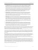
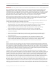
DATA CENTER and CAMPUS NETWORKS DEPLOYMENT GUIDE Figure 11 Network with associated latencies. Voice calls were made using (1) the soft clients, (2) the Polycom CX700 phones, and (3) High Definition video calls: 1. From Seattle to all the remote sites 2. From San Francisco to all the remote sites 3. From New York to all the remote sites 4. From Austin to all the remote sites 5.
DATA CENTER and CAMPUS NETWORKS DEPLOYMENT GUIDE Overall, the test was successful. By implementing a Microsoft Lync Server 2010 on a Brocade network infrastructure, customers can feel confident that they can have a successful deployment. In addition, the call quality and experience are significantly better than Microsoft Communication Server 2010. Details are provided below (scores are averaged to summarize the results). Table 7.
DATA CENTER and CAMPUS NETWORKS Average Score DEPLOYMENT GUIDE With Average Jitter Average Delay Average Packet Loss Average MOS New York to all sites using soft client 5% packet loss 6.33 53.00 6.17 4.06 Video between HQ and New York 10% 1.00 50.00 10.00 3.
DATA CENTER and CAMPUS NETWORKS DEPLOYMENT GUIDE REFERENCES The following resources were consulted to perform the solution testing: • Brocade NetIron Configuration Guide (MLX) • Brocade VDX Configuration Guide • Brocade ServerIron ADX Configuration Guide • Brocade SAN Design Guide • Brocade FastIron Configuration Guide (FCX, SX, ICX) • Performance Profile for Microsoft Lync Server 2010 • Microsoft Quality of Experience Guide: http://www.microsoft.com/downloads/en/confirmation.
DATA CENTER and CAMPUS NETWORKS DEPLOYMENT GUIDE APPENDIX: SWITCH CONFIGURATIONS ISP Provider ver V2.4.0eT143 trust dscp module 1 rx-bi-1g-24-port-copper module 2 rx-bi-1g-24-port-fiber module 3 rx-bi-10g-4-port module 4 rx-bi-10g-4-port no spanning-tree vlan 1 name DEFAULT-VLAN hostname SPCORE router ospf area 20 area 30 area 40 area 11 redistribution connected redistribution static interface management 1 ip address 209.157.22.254/24 interface ethernet 1/1 port-name to hq ip ospf area 11 ip address 10.
DATA CENTER and CAMPUS NETWORKS DEPLOYMENT GUIDE access-list 101 permit ip any any 802.1p-priority-matching 3 dscp-matching 30 access-list 101 permit ip any any 802.1p-priority-matching 0 end New York Current configuration: ver 07.0.
DATA CENTER and CAMPUS NETWORKS interface ethernet 0/1/1 trust dscp ip access-group 101 in ip address 10.30.57.1 255.255.255.0 ip helper-address 1 10.10.57.2 ip ospf area 30 interface ethernet 0/1/33 load-interval 30 trust dscp interface ethernet 0/1/34 inline power trust dscp interface ve 31 ip access-group 101 in ip address 10.31.57.1 255.255.255.0 ip helper-address 1 10.10.57.
DATA CENTER and CAMPUS NETWORKS ip access-group 101 in ip address 10.41.57.1 255.255.255.0 ip helper-address 1 10.10.57.3 access-list 101 permit ip any any dscp-matching access-list 101 permit ip any any dscp-matching access-list 101 permit ip any any dscp-matching access-list 101 permit ip any any dscp-matching access-list 101 permit ip any any dscp-matching DEPLOYMENT GUIDE 40 30 48 40 0 traffic-policy audio 802.1p-priority-marking 3 802.1p-priority-marking 7 802.
DATA CENTER and CAMPUS NETWORKS DEPLOYMENT GUIDE server port 5061 tcp server port 5063 tcp server port 135 tcp server port 80 tcp server port 443 tcp server port 444 tcp server port 5069 tcp server source-nat server source-nat-ip 192.168.10.251 255.255.255.0 0.0.0.0 port-range 2 server router-ports ethernet 1 server router-ports ethernet 2 context default server real EEFE2 192.168.10.
DATA CENTER and CAMPUS NETWORKS DEPLOYMENT GUIDE bind sip EEFE1 sip EEFE2 sip bind 5069 EEFE1 5069 EEFE2 5069 bind 5063 EEFE1 5063 EEFE2 5063 vlan 1 name DEFAULT-VLAN by port vlan 999 by port untagged ethe 16 no spanning-tree vlan 5 by port vlan 10 by port tagged ethe 1 to 2 no spanning-tree aaa authentication web-server default local no enable aaa console hostname ADX1 ip address 10.10.57.17 255.255.255.0 ip default-gateway 10.10.57.254 telnet server username admin password .....
DATA CENTER and CAMPUS NETWORKS DEPLOYMENT GUIDE Four regions and sites are represented in Figure 11: Seattle, San Francisco, Austin, and New York. 1. Create network regions. Each region has a specified central site.
DATA CENTER and CAMPUS NETWORKS 4. DEPLOYMENT GUIDE For each subnet in the topology, specify the associated network site. Every subnet in the network topology must be associated with a specific network site, because subnet information is used to determine the network site on which an endpoint is located. When the locations of both parties in a session are known, CAC can determine whether or not there is sufficient bandwidth to establish a call.
DATA CENTER and CAMPUS NETWORKS DEPLOYMENT GUIDE New-CsNetworkBandwidthPolicyProfile -Identity 25Mb_Link –Desription “BW profile for 25Mb links” -AudioBWLimit 10000 -AudioBWSessionLimit 200 -VideoBWLimit 7000 VideoBWSessionLimit 700 7. Create network sites.
DATA CENTER and CAMPUS NETWORKS DEPLOYMENT GUIDE Links from San Francisco: New-CsNetworkRegionLink -NetworkRegionLinkID SanFrancisco_Austin -NetworkRegionID1 SanFrancisco -NetworkRegionID2 Austin -BWPolicyProfileID 5Mb_Link New-CsNetworkRegionLink -NetworkRegionLinkID SanFrancisco_NewYork -NetworkRegionID1 SanFrancisco -NetworkRegionID2 NewYork -BWPolicyProfileID 5Mb_Link Links from Austin: New-CsNetworkRegionLink -NetworkRegionLinkID Austin_NewYork -NetworkRegionID1 Austin -NetworkRegionID2 NewYork -BWP
DATA CENTER and CAMPUS NETWORKS DEPLOYMENT GUIDE © 2012 Brocade Communications Systems, Inc. All Rights Reserved. 03/12 GA-DG-435-00 Brocade, Brocade Assurance, the B-wing symbol, DCX, Fabric OS, MLX, SAN Health, VCS, and VDX are registered trademarks, and AnyIO, Brocade One, CloudPlex, Effortless Networking, ICX, NET Health, OpenScript, and The Effortless Network are trademarks of Brocade Communications Systems, Inc., in the United States and/or in other countries.