
Technical data


DATA CENTER and CAMPUS NETWORKS DEPLOYMENT GUIDE
Deploying Brocade Networks with Microsoft Lync Server 2010 15 of 52
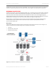
access layer includes devices such as workstations, VoIP phones, and notebooks, which do not typically require the
same performance demands as servers require in the data center.
However, the campus LAN access layer requires PoE and PoE+ for IP phones. In most cases 1 GbE is sufficient to
meet most client demands.
Since the access layer puts many demands on the network, scalability, high performance, reliability, PoE, and other
advanced features are required. Layer 2 is typically deployed at this level, because it allows a company to scale and
servers and services to communicate more efficiently. The typical features configured at this layer are ACLs, QoS,
CoS/DSCP, STP, LLDP-MED, and PoE.
In some cases, network architects have deployed Layer 3 in the access layer to take advantage of Layer 3 benefits.
These include:
• Server stability and application isolation
• All uplinks available up to the ECMP maximum
• Fast uplink convergence in the event of a failure
• Reduction of broadcast domains
It is critical that you have reliable and deterministic switches that can quickly converge when outages occur. Outages
are inevitable, but having a solid design and robust Brocade switches keeps your network up and running without
affecting applications.
NETWORK SERVICES BEST PRACTICES FOR UNIFIED COMMUNICATIONS
Spanning Tree
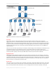
Spanning Tree Protocol (STP), invented over 25 years ago, still plays a critical role in today’s network deployments.
STP is a Layer 2 protocol that eliminates redundant paths in a network. It discovers loops and then makes a decision
about which path will be used and which path will be shut down. How is this decision made? The root bridge is the
switch that decides. By default, the switch with the lowest Bridge ID (which is a combination of the switch priority
followed by the MAC address of the switch) becomes the root bridge. All Brocade switches have a default priority
of 32,678.
A disadvantage of STP is the reconfiguration and convergence time needed to recalculate optimal routes when a
switch fails. Typically, if the default Spanning Tree is used, this can take about a minute, depending on the network
size. During the convergence, applications go offline. Even though applications are built to handle a small amount of
downtime, a voice call would most likely get dropped during this convergence. Rapid Spanning Tree (RST, IEEE
802.1w) was invented to reduce the amount of time it takes to converge. RST is not based on any timer value.
Rather, it is based on the explicit handshakes between directly connected inter-switch ports to determine their role
as either a Designated Port or a Root Port. Hence, with port roles assigned sooner, the convergence time is less
than 500 ms.
NOTE: This rapid convergence does not occur on ports connected to shared media devices, such as hubs. To take
advantage of the rapid convergence provided by 802.1w, make sure to explicitly configure all point-to-point links
in a topology.
The Brocade implementation of 802.1w allows ports that are configured as edge ports to be present in an 802.1w
topology. Edge ports are ports of a bridge that are connected to workstations or computers. Edge ports do not
register any incoming Bridge Protocol Data Units (BPDU) activities. Edge ports assume Designated Port roles. Port
flapping does not cause any topology change events on edge ports, since 802.1w does not consider edge ports in
the Spanning Tree calculations.
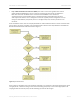
When ports are configured for point-to-point, the switch knows that it is connected to another neighboring switch that
is also participating in RST. Configuring switches for point-to-point allows convergence to take place in about