
Technical data


DATA CENTER and CAMPUS NETWORKS DEPLOYMENT GUIDE
Deploying Brocade Networks with Microsoft Lync Server 2010 16 of 52
500 ms, because ports that are participating in RST are known. Both voice and video can handle this amount of
downtime without affecting performance.
Brocade Layer 2/3 switches also support Per VLAN Spanning Tree (PVST). PVST is enabled in each VLAN as it is
enabled on a Layer 2 switch. In this case, each VLAN has its own instance of Spanning Tree and its own root bridge.
For example, if you have two VLANs, 10 and 20, VLAN 10 can have a different root bridge from VLAN 20.
To enable 802.1w for all ports in a port-based VLAN, enter commands such as these:
FastIron(config)#vlan 10
FastIron(config-vlan-10)#spanning-tree 802-1w
To configure a point-to-point port for 802.1w, enter commands such as these:
FastIron(config)#vlan 10
FastIron(config-vlan-10)#spanning-tree 802-1w e 9 admin-pt2pt-mac
To configure an edge port for 802.1w, enter commands such as these:
FastIron(config)#vlan 10
FastIron(config-vlan-10)#spanning-tree 802-1w e 9 admin-edge-port
We recommend that you use Rapid Spanning Tree Protocol (RSTP) with Microsoft Lync Server 2010. With
convergence time of about 500 ms, voice and video stay active with changes in the network, for example, when a
switch dies, computers are plugged into the network, or new switches are connected to network. If users are on a
voice call when a network switch dies with 802.1d Spanning Tree in place, the call is disconnected. Rapid Spanning
Tree (RPST), on the other hand, can converge fast enough such that Microsoft Lync Server 2010 can handle the brief
outage and the call is not dropped.
When configuring RSTP, be sure that you configure all the ports that are connected to other switches as a point-to-
point connection. For all end devices, such as workstations, laptops, and VoIP phones, configure the switch as an
edge port.
VRRP and VRRP-e
Virtual Router Redundancy Protocol (VRRP) is a non-proprietary redundancy protocol designed to increase the
availability of the default gateways servicing hosts on the same subnet. This increased reliability is achieved by
advertising a “virtual router” as a default gateway to the hosts, instead of one physical router. Two or more physical
routers are then configured to represent the virtual router, with only one doing the actual routing at a given time. If
the current physical router that is routing the data on behalf of the virtual router fails, an arrangement is made for
another physical router to automatically replace it.
Traditionally, if a host default gateway goes offline, the network administrator needs to manually change the default
gateway, which is relatively simple if there are only a few hosts. But when there are hundreds or thousands of hosts,
it is an extremely complicated and cumbersome operation. Since both voice and video require the network, it is very
important that the network be robust and always online.
VRRP-e is a Brocade-enhanced version of VRRP that overcomes limitations in the standard protocol. With VRRP-e all
routers are backups for a given redundancy group, in which the router with the highest priority becomes master.
VRRP-e uses User Datagram Protocol (UDP) to send multicast “Hello” messages, and the VIP must be a unique
address on the same subnet on which VRRP-e is enabled.
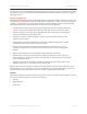
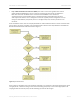
VRRP-e, shown in Figure 5, is unlike VRRP in the following ways:
• There is no “owner” router. You do not need to use an IP address configured on one of the Layer 3
Switches as the Virtual Router ID (VRID), which is the address you are backing up for redundancy. The
VRID is independent of the IP interfaces configured in the Layer 3 Switches. As a result, the protocol
does not have an “owner,” as VRRP does.
• There is no restriction on which router can be the default master router. In VRRP, the “owner” (the
Layer 3 Switch on which the IP interface used for the VRID is configured) must be the default master.