
Instruction manual

A
lfaSpid Rotator RAK1 http://Alfaspid.com http://www.hy-gain.com Page 16
Page 16 of 21
A
lfaSpid Rotator RAK1
http://Alfaspid.com http://www.hy-gain.com
Copyright
A
lfaRadio Ltd. 2002-2008
Be careful not to over wind your coax with the next test, as there will be no protection
from over turning.
Find a small 12 volts supply which will deliver 3 to 4 amps. ( a small 12 Volt battery
will work just fine )
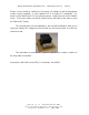
To confirm that the motor runs you may connect 12 volts D.C. to the lines that go to
the motor, pins 1 and 2, it should turn. Reversing the 12 Volts D.C. should cause the
motor to turn in the reverse direction.
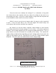
To confirm that the sense circuit in the rotator is working, connect an ohm meter to the
senses lines pins 3 and 4, apply 12 volts to the motor lines pins 1 and 2; you should
see the ohm meter reading alternate between open circuit and about 1200 ohms while
the motor is turning.
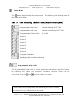
Pin on Rotator not
controller Typical Reading
Your
reading
Pins 1 to 2 About 2 to 4 Ohms ________
Depends on the length of
wire to rotator
Pins 3 to 4 Open or 1200 Ohms ________
Depends on the status of
the read switch
Pins 1 to 3 Open ________
Pins 2 to 3 Open ________
Pins 2 to 4 Open ________
________
Pin 1 to Ground Open ________
Pin 2 to Ground Open ________
Pin 3 to Ground Open ________
Pin 4 to Ground Open ________
________
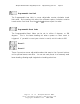
Voltage on controller
Pins 1 to 2 About 12 volts with motor running
Depends on the supply
voltage (14 volt applied)
Pins 3 to 4
About 8.5 volts or 2.5
volts *
Depends on the status of
the read switch
and the Supply voltage