
User manual

AlfaSpid Rotator www.alfaradio.ca Page 14
Copyright Alfa Radio Ltd. 2008-09-15 www.alfaradio.ca 780 466 5779 Alfaspid-AZ-EL-2008-08-15-manual.doc
Be careful not to over wind your coax with the next test, as there will be
no protection from over turning.
Find a small 12 volts supply which will deliver 3 to 4 amps. ( a small 12 Volt
battery will work just fine )
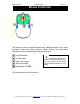
To confirm that the motor runs you may connect 12 volts D.C. to the lines that
go to the motor, pins 1 and 2, it should turn. Reversing the 12 Volts D.C. should
cause the motor to turn in the reverse direction.
NOTE: ON THE ELEVATION ROTATOR THERE ARE MECHANICAL
SWITCHES WHICH REMOVES THE POWER TO THE MOTOR WHEN THE
END LIMIT IS REACHED. A DIODE IS PLACED IN SERIES WITH THE
MOTOR. TO TEST FOR THIS REVERSE THE POWER TO THE MOTOR, THE
UNIT SHOULD TURN.
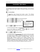
To confirm that the sense circuit in the rotator is working, connect an ohm
meter to the senses lines pins 3 and 4, apply 12 volts to the motor lines pins 1
and 2; you should see the ohm meter reading alternate between open circuit and
about 1200 ohms.
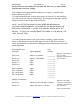
Pin on Rotator not
controller Typical Reading
Your
reading
Pins 1 to 2 About 2 to 4 Ohms ________
Depends on the length of
wire to rotator
Pins 3 to 4 Open or 1200 Ohms ________
Depends on the status of
the read switch
Pins 1 to 3 Open ________
Pins 2 to 3 Open ________
Pins 2 to 4 Open ________
________
Pin 1 to Ground Open ________
Pin 2 to Ground Open ________
Pin 3 to Ground Open ________
Pin 4 to Ground Open ________
________
Voltage on controller
Pins 1 to 2 About 12 volts with motor running
Depends on the supply
voltage (14 volt applied)
Pins 3 to 4 About 8.5 volts or 2.5 volts
Depends on the status of
the read switch
and the Supply voltage