
Instruction manual


f--
f--
~~
t t
t
~
t~
t
--}
~
t
~~
t t
(a)
00
III
011
00
III
III
00
100
100
00
100
001
00
100
001
00
100
001
00
011
100
00
III
III
00
110
010
(b)
0011
1011
0011
1111
0010
0100
0010
0001
0010
0001
0010
0001
0001
1100
0011
1111
0011
0010
(c)
3B
3F
24
21
21
21
Ie
37
32
(d)
1)
Select the position in memory
at which the shape table is to
be
stored.
2)
Generate and display the work-
ing
(15
x
15)
grid.
3)
Input the starting coordinates
for the shape (required for justification).
4)
Generate the proper 3-bit
cOQes
that represent the
plotting
vectors, bas-
ed
on
the keystrokes used to input the
pattern.
5)
Assemble the 3-bit codes (in
groups
of
two
or
three, depending upon
APPLE'S strictures) into a byte.
6)
Store the assembled byte in the
shape table.
7)
Provide for proper finishing-off
of
the current byte when the Quit key is
hit.
8)
Add
an
end-of-record mark ( a
zero byte) required
by
APPLE as a shape
terminator.
9)
Store the table.
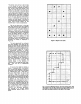
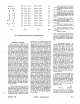
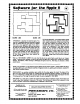
Fig.
3:
Translation
of
shape vectors
to
Hexidecimal Code
Most
of
these steps are straightfoward,
but two
of
them, generation
of
the 3-bit
codes
that
represent
plotting
vectors,
and their assembly into bytes (steps 4
and
5,
above), require further elabora-
tion.
\
j
Approach
to
a Solution
Every computer programmer has
his
own mind-set. For some, it is struc-
ture: a beautiful program
that
reads like
a novel. For
others-start
at the middle
and develop a nice, tight, efficient
algorithm. I am
an
input-output bug. To
me,
the proper questions
that
should
be
first
answered are: how can I make it
easy
for
the user
of
the program
to
get
his
data
into
the program; and how can
the
output
be made digestible? In the
present case,
of
course, the major pro-
blem is one
of
input. With the equipmant
at
hand-an
APPLE keyboard, video
screen and a couple
of
floppy
disks-I
settled on a display of a
15
x
15
grid and
a cursor that can
be
moved by
hitting
ap-
propriate keys (Up, Down, Left, and
Right). The shape is
cneated
by
plotting
the shape as a dot paUern under control
of the moveable cursor, using the P (for
Plot) key
to
lay down the
dot
pattern.
One necessary key is the Quit key, which
informs
the
computer
that
the shape is
done. A convenience key, E for Erase is
provided to accomodate some of my
sloppy keyboard habits; it
facilitates
un-
doing the
last
plotted point. The selec-
tion
of
keys U,D,L and R for directing the
cursor was modeled
after
the set
of
allowed plotting vectors (there are no
diagonal moves in the set), and was a
fortunate selection for easy
formulation
of
the algorithm.
While the general format for input
was
quite
clear, the approach
to
translating
that
input into a shape table
was not immediately clear. Two pro-
ceedures are possible: you can store all
of
the input data in some sort
of
two-
dimensional array in memory and then
December,
19179
analyze it,
or
you can take the input data
as they are acquired and develop the
shape table on the fly. I seriously con-
sidered the first path, and in fact, wrote
a program
that
would translate the input
pattern into a matrix
of
zeroes and ones.
Further
consideration
showed
that
analysis
of
the pattern would
be
dif-
ficult, one
of
the major problems being
that
of
ensuring proper
plotting
of
the
shape with respect to
its
starting point,
I.e.,
justification.
Moreover,
the
most ef-
ficient
approach in terms
of
processing
time and storage requirements for the
shape table is to confine generation of
the plotting vectors to the occupied cells
of
the grid as much as possible. Such
pattern tracing on
an
arbitrary
two
dimensional array presents a formidable
search
problem,
particularly
with
disconnected patterns. The solution of
the problem
of
efficienly tracing the in-
put pattern was obvious as soon as I
realized
that
the keystrokes used by a
person entering the pattern on the grid
constituted
a continuous record
of
the
pattern. By analyzing the keystroke pat-
tern, I could produce a string
of
equivalents. The inspiration for
this
may
be
tracable in part to my knowledge
of
the way in which chemical structures
are recorded at Chemical Abstracts Ser-
vice of the American Chemical Society,
where chemical typewriters, used for
creating chemical structures, are con-
nected to computers which record the
keystrokes
of
the operator entering the
structure. The recored of keystrokes can
then be
"played
back"
to reproduce the
structure
exactly as it was keyed in.
With
this
basic approach decided upon,
the outline
of
the required algorithm
became clear:
MICRO
--
The
6502
Journal
In
APPLESOFT
BASIC,
the
character returned
by
a keystroke is ac-
cessible with a
"GET"
command; the in-
struction
GET KEY$
will
load the
character
accessed
by
the
next
keystroke
into
the variable
KEY$.
We
may
examine
KEY$
to
determine
whether it contains a
"D"
"L"
"U"
or
"R"
and then do a table
I~ok-~p
(uS'ing
the
definitions
in Figure
4)
to
retrieve the
decimal value associated with the direc-
tion implied
by
the keystroke. Each
decimal value,
of
course, as stored in
memory will generate the proper 3-bit
binary
code.
Subsequently,
the
keystroke preceding the current one
(which we
thoughtfully
saved in variable
KSVE$) is examined. If
KSVE$
is a
"P",
then
the
current 3-bit code must repre-
sent
a
plot-then-move
vector
and
decimal 4 us added to the deciaml factor
for the current key. If
KSVE$
is not a
"P",
then the current decimal key equivalent
remains unaltered.
Assembly
of
the 3-bit codes into
bytes involves only basic consideration
of
decimal
to
binary conversion. Byte
assembly is done in the program as each
3-bit code becomes available, but for the
purposes
of
discussion, let us assume
that 3-bit codes,
V"
V"
V,
are available in
that
order
from
the
last
three
keystrokes. The
first
3·bit code in-
itializes the byte:
V,
,..-..
BYTE = V\
OOOOOXXX
The second 3·bit code must
be
added to
the byte,
but
must first
be
left-shifted
three bits
if
the
V,
bits already present
19:13