
Instruction manual
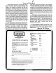

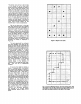
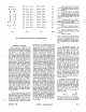
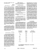


Fig.
5:
Memory Map
for
Shape Table
Shape File Initialization
The principle shape-creating pro-
gram requires a previously allocated
disk file
for
shape table storage. The in-
itialization program (Figure
6)
creates
the
disk
file and also establishes the
name and length
of
the file. The program
allocates space for the shape table
directory based on the number
of
shapes
to
be
stored in the file, a number
that
is declared by you during initializa-
tion. The memory
map_
for a shape table
is stored in the first byte
of
the table; its
maximum value is therefore
255,
and
this
is the maximum number
of
shapes
that
can be'stored in one shape table.
The directory contains addressing infor-
mation
that
allows random access
to
r
)
\
J
N,
No. shapes
Empty
Directory
First Shape
Byte 1
Byte 2
2* N Bytes
any shape in the table.
The directory falls between the first
byte
of
the table and the beginning
of
the
first
shape. The amount
of
space
allocated to the directory is determined
by
the number
of
shapes ultimately
to
be
stored in the table; each shape requires
two
byte in the directory for addressing.
The shape tables themselves may
be
any length, up to a total length consis-
tent
with
the
15
x
15
matrix in which the
shapes are created. The shape tables
are stored end-to-end as they are added
to the file, each shape determining in a
zero byte as end-of-record mark. The
layout
of
the shape file requires
that
any
tables added to the file be accurately
done, because once a table is buried in
the file, it cannot
be
simply replaced
unless the replacement has precisely
the same length.
The file initialization program is
also used for creating the cursor
re-
quired
for
mapping shapes on the
15
x
15
working grid produced by the
principal program. This relieves the user
of
the need to generate the cursor
himself everytime
he
opens a new shape
file. The cursor is stored as the first
shape in the shape file, and the shape-
creating program assumes
that
the cur-
sor has already been stored
for
its use.
As a consequence
of
this arrangement,
you
must
remember
that
the user-
generated shapes start with the second
shape table in the file.
Although the file initialization pro-
gram zeroes out all
of
the bytes in the
directory, there is no substantial reason
for
doing this, except
that
the string
of
zero bytes make
it
easy
to
determine
where the directory ends and the shape
tables begin in a memory dump. This ad-
vantage will last only until the directory
is filled.
The
Shape Creating Program
The BASIC program (Figure
7)
that
enables shape generation requires the
use
of
dual floppy disks, but can
be
easi-
ly changed
for
single floppy use by
replacing
"02"
in step
110
by
"01."
(Similar adjustments will have
to
be
made in the initialization and display
programs, which store and access the
shape file from
disk
02). Tape users will
have
to
replace disk
1/0
by
suitable tape
I/O
in
steps
100,
110
and
1360.
The program loads a pre-existing
shape file (created
by
the initialization
program, if necessary) from disk, using
the shape file name supplied by you on
request from the program. The file is
loaded
into
a memory location which
you are also asked for by the program. A
check is made (step
220)
that
there is
room in the shape file
-directory for
another entry.
If
not, you will be so advis-
ed
and the program will abort. A pointer
to the shape file required by the APPLE
system is set up in step
260.
The
15
x
15
plotting grid is turned on (steps
300-330)
and you will be asked to input the star-
ting grid coordinates for the shape.
Note, these are
grid
coordinates and
not
screen coordinates
that
are asked for.
The cursor will
be
displayed on the
center
of
the grid square
that
you have
just selected as the starting point. Some
user helps are displayed in the text area
under the grid (steps
410-440),
and you
are
off
and running. Manipulation
of
the
R,L,D, and U keys will move the cursor in
the appropriate directions. The REPEAT
key will work with these commands.
Pressing the P key will plot a small circle
inside the square in which the cursor
currently resides, and this plotted point
will become part
of
the shape table
be-
ing built in memory.
An
image
of
the cur-
sor will persist in the initial
square-as
a
"negative"
image if you happened
to
plot
at
that square. The persistent cur-
sor image serves as a reminder
to
you
of
the location
of
the start
of
the shape.
The cursor is made to disappear and
reappear in adjacent squares as you
press the move keys by XDRAW com-
mands at steps
500
and
530;
the IF state-
ment at step
1040
in the subroutine
that
draws the
plotting
circle is responsible
for keeping the persistent image
of
the
cursor
at
the starting square. The flag,
FLAG,
that
appears in step
480
and
elsewhere is used to allow the cursor
to
be
turned
off
in a plotted square and
to
be
turned on again when the cursor
moves to the next square.
Keystrokes are recorded in step
570.
A previous step
(550)
saves the
previous two keystrokes in KI$ and
KSVE$. The former record, KI$, is
re-
quired to allow the erase feature, con-
trolled by the E key and discussed
below.
KSVE
is needed
for
proper
generation
of
plot-then-move
3-bit
codes, also discussed below. Interpreta-
tion
of
a keystroke takes place in steps
590-710, a sequence
of
IF's called a
sieve. This particular form
of
key screen
was chosen because it gives almost
complete protection against inadvertent
entry
of
incorrect keys. Once you are in
the program, you will find
that
the
keyboard is effectively locked out for all
keys except those required by the pro-
gram. If a non-applicable key is pressed,
the sieve eventually routes the program
through step
710
back
to
another key ac-
cess
at
step
570.
Inside the sieve, when
a keystroke has bee identified as a move
command (L,R,U,D), the appropriate
X-
or
Y-
coordinate adjustment is made and
the decimal value
of
the 3-bit code ap-
plicable
to
the move is stored where the
variable
KSVE$
is checked
to
see
if
the
previous keystroke was a Plot com-
mand.
If
it
were, SYMBOL is in-
cremented by a 4 (remember Figure
4?),
and SYMBOL is then transmitted to the
byte assembly area, more of this later.
December,
1979'
MICRO
--
The 6502 Journal
19:15