
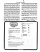
Instruction manual

If
the
current
keystroke
cor-
responds not
to
a move command, but
to
a Plot command, the program sets the
cursor disable flag, FLAG, calls the plot
subroutine and then branches back
to
get the next keystroke (all
of
this
is done
in step
680).
The Quit command forces a
branch
to
a routine
that
closes
out
the
current byte (starting at step
1080),
adds
a record mark (step
1170)
and draws
thew completed shape (step
1170).
At
this
juncture, you are asked a series
of
questions, the answers to which will
allow you to:
1)
forget the current shape and go
back and try again
without
re-accessing
the current shape file from disk;
2)
keep the current shape, update
the shape file directory and start a new
shape;
3)
forget the whole
thing-add
no
new shapes to the file and quit;
4)load an updated shape file
to
disk and quit.
These alternatives will help you to avoid
filling up
the
shape table
with
unwanted
shapes, and
allow
you
to
experiment
without
being forced
to
save all
of
your
experiments.
The closing
out
of
the current byte
preparatory to ending the current shape
definition
(step
1080)
poses a problem
if
the last keystroke is a Plot command
because a P command alone does not
generate a vector. There is nothing
to
store after a final P command, unless
it
is followed by some sort
of
move. The
problem is handled in steps 1100-1140 by
adding an arbitrary up-move after a final
Plot command
to
generate a plot-then-
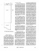
move-up vector. (Note
that
in the illustra-
tion Figure
2,
the concluding vector is a
plot-then-move-down. This was done for
the sake
of
clarity in drawing only. The
point
is mentioned in case
some
unusually perceptive reader notices
that
the foregoing description does not tally
with the example in Figure
2).
The final
vector is either added
to
the current
byte, in which it will appear as the only
entry. If the last keystroke prior
to
clos-
ing the current shape table is anything
other than a Plot command, the current
byte can
be
closed out immediately
without
further ado.
The erase command has the very
limited
capability
of
erasing the last Plot
command only. As discussed before, a
Plot command alone does
not
result in
formation
of
a vector
until
it is followed
by
a command. Therefore,
if
a Plot com-
mand is issued in error and no move
command
follows
it, no vector will
be
generated and
the
shape table remains
unchanged at this point. It is therefore
possible
to
undo the Plot command
simply,
without
the
complication
of
19:16
analyzing the
last
byte for returning to
the
state
that
preceeded the mistaken
command
(and
it
would
be
complicated! i). At the point at which the
Plot command is mistakenly issued,
KSVE$ has a certain value. If we wish
to
go back
to
the condition prior
to
the
mistaken Plot command, we
must
restore that value
to
KSVE$ so
that
when
the correct command is issued it is pro-
perly interpreted when KSVE$ is examin-
ed
subsequently. The character required
for
this
purpose lies waiting in KI$. Thus,
the erase command loads
this
previous
value
into
KSVE$ and
"unplots"
the in-
correct
plotting
circle
by
re-plotting with
the color
"black"
(HCOlOR = 0 in step
720).
Note
that
because
of
these limita-
tions, no plot command can be undone
after
a move has been made.
Byte assembly using the 3-bit codes
(stored currently in SYMBOL)
occurs
in
780-980. The variable CYCLE keeps track
of
the number
of
3-bit codes entered
into
the current byte (called BYTE in the pro-
gram).
After
the second 3-bit code is
loaded
into
BYTE (step 820) a check is
made (step 840)
to
see
if
the byte is less
than
8;
if
it is, we know
that
the byte con-
tains an unrecognizable move-up vector
in the
left
five bits. In
that
case, a dum-
my move-right 3-bit code is inserted
into
the byte,
the
byte
is
stored (step 860) and
a new byte
is
formed consisting
of
the
required move-up
(000)
followed by a
dummy move-left
(110)
to
compensate
for
the
dummy move-right. The resulting
byte contains the
bit
string
0001
1000,
decimal
24,
generated in step
880.
Statements 950·980 take care
of
the
cases in which the third 3-bit code is a
plot-then-move code or a move-up only
code, which require that the current byte
be
stored, and the current 3-bit code
be
loaded
into
the next byte.
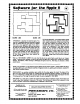
The Display Program
It
is likely
that
your
disk
or tape will
be
replete
with
shape files tailored to
various uses, now that creating shape
tables is so easy. A convenient display
program
will
become essential in order
to
find
out
which shapes are stored
where. The display program
that
ac-
complishes this (Figure
8)
is
an
example
of
how shape files may
be
used is a pro-
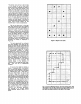
gram. The program constructs a 6
x 6
grid on the high resolution screen and
displays one shape per grid cell. To iden-
tify
the
location
of
the shapes in the
shape table, each occupied cell carries
the shape index in the upper left-hand
corner. The numerals required for plot-
ting these indices are extracted from a
shape table called NUMERALS
that
you
will have
to
create at storage location
20000 (decimal) by means
of
the shape
creating program. The numerals are
restricted
to
a 5 x 7 grid, and are format·
ted as illustrated
by
the example in
MICRO
--
The 6502 Journal
Figure
1.
Sufficient
space is reserved in
the display squares
to
accomodate
three-digit numerals from 1 through
255.
"Aha,"
you ask,
"how
can
255
shapes
be
displayed in a 6 x 6 grid?" The program
provides for paging through the shape
table,
36
shapes
at
a time. The paging is
activated by
hitting
any alphanumeric
key on the APPLE keyboard.
The display program opens
by
get-
ting the shape files
that
it
needs-one
for numerals (step
50)
and the table
to
be
displayed (step
90).
Pointers
to
the
tables are set up (steps
70
and
120).
Starting
at
step
180,
each shape I is ac-
cessed in a
FOR.
..
NEXT loop. A grid-
specific
index
is
calculated (step
190)
by
taking
the
current shape index I modulo
36(step
190).
For
the
first shape in each
group
of
36
(I
modulo
36
=
1),
the screen
is cleared (step
240)
and the 6 x 6 grid is
displayed (steps 250-330). The row and
column
positions
for the
I-th
shape in
the grid are found (steps
360,
370).
The
shape index is
"unpacked"
into
its
separate
digits
(steps 380-410) and these
digits
are plotted in the correct grid cell
in
the
upper left-hand corner (steps
430-480).
The NUMERALS shape table is
accessed in step
420
by placing the
pointer
to
the NUMERALS shape table in
(decimal) addresses 232 and
233,
so
that
subsequent DRAW commands will refer
to
this
table. In
similar
fashion, when the
shapes to be plotted are required, the
address
of
the shape table must
be
entered
into
addresses
232,
233.
This
program
illustrates
how any number
of
shape tables may
be
used inside a pro-
gram simply
by
supplying the correct
pointers at the time that shapes are
to
be
DRAWn or XDRAWn.
Parting Words
The
15
x
15
grid used for shape
creation is the largest practical size for
the APPLE screen with space provided
for text. A larger grid can
be
accomodat-
ed
by
eliminating the
text
area, but this
will compromise the required starting
coordinate input. However, the number
of
cells could
be
increased
by
decreas-
ing cell size and using a smaller plotting
figure. If you try this, it is convenient
to
select a plotting grid
with
odd numbers
of
X and Y segments so
that
the central
plotting
area falls
on
a grid square and
not at the intersection
of
two
grid lines.
This is
of
help in centering shapes.
You
should also
be
aware, if
it
is not
obvious by now,
that
the location
of
a
shape on the grid has no bearing on
where
it
plots
in high
resolution
graphics, except with regard
to
the in-
itial point
of
the shape, which alone
determines
justification.
You may use
any convenient subsection
of
the full
grid for plotting, and it does not have to
be the same subsection for each shape.
continued on page
19
December, 1979