Operating Manual MC-Series MCR-Series WHISPER MCS-Series MCV-Series Precision Gas Mass Flow Controllers The Fastest Flow Controller Company in the World!
FULL TECHNICAL SUPPORT | LIFETIME WARRANTY RECALIBRATION Your Alicat instrument is a precision device and Alicat strongly recommends that you send it to us on a yearly basis for recalibration. A yearly recalibration does a few things: ► It insures that your unit is functioning according to specification. ► Contamination may cause the instrument to measure flow improperly. Recalibration insures the instrument is clean and free from debris.
Thank you for purchasing an Alicat Gas Flow Controller. Please take the time to read the information contained in this manual. This will help to ensure that you get the best possible service from your instrument.
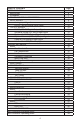
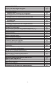
TABLE OF CONTENTS GETTING STARTED MOUNTING PLUMBING POWER AND SIGNAL CONNECTIONS INPUT SIGNALS Analog Input Signal RS-232 / RS-485 Digital Input Signal OUTPUT SIGNALS RS-232 / RS-485 Digital Output Signal Standard Voltage (0-5 Vdc) Output Signal Optional 0-10 Vdc Output Signal Optional Current (4-20 mA) Output Signal Optional 2nd Analog Output Signal Information for Alicat TFT (Color Display) Instruments DISPLAYS AND MENUS MAIN Gas Absolute Pressure Gas Temperature Set-Pt.
TABLE OF CONTENTS RS-232 or RS-485 Output and Input Configuring HyperTerminal® Streaming Mode Changing from Streaming to Polling Mode Sending a Set-Point via RS-232 or RS-485 To adjust the P & D terms via RS-232 or RS-485 Gas Select Collecting Data Data Format Sending a Simple Script File to HyperTerminal® Operating Principle Standard Gas Data Tables Gas Viscosities, Densities and Compressibilities at 25o C Gas Viscosities, Densities and Compressibilities at 0o C Troubleshooting Maintenance and Recalibratio
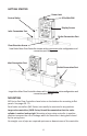
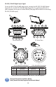
GETTING STARTED Power Jack Control Valve 8 Pin MiniDIN Display Screen Inlet Connection Port Outlet Connection Port Flow Direction Arrow Small Valve Mass Flow Controller shown with an upstream valve configuration and connection port fittings Inlet Connection Port Outlet Connection Port Large Valve Mass Flow Controller shown with a downstream valve configuration and connection port fittings MOUNTING MC-Series Gas Flow Controllers have holes on the bottom for mounting to flat panels. See pages 50- 70.
PLUMBING Your controller is shipped with plastic plugs fitted in the port openings. To lessen the chance of contaminating the flow stream do not remove these plugs until you are ready to install the device. Make sure that the gas will flow in the direction indicated by the flow arrow. Standard MC-Series Gas Flow Controllers have female inlet and outlet port connections. Welded VCR and other specialty fittings may have male ports.
POWER AND SIGNAL CONNECTIONS Power can be supplied to your controller through either the power jack (power jack not available on CSA/ATEX approved devices) or the 8 pin Mini-DIN connector. An AC to DC adapter which converts line AC power to DC voltage and current as specified below is required to use the power jack. Small Valve controllers require a 12-30Vdc power supply with a 2.1 mm female positive center plug capable of supplying 250 mA. NOTE: 4-20mA analog output requires at least 15 Vdc.
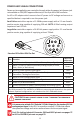
INPUT SIGNALS Analog Input Signal Apply analog input to Pin 4 as shown on page 8. For 6 Pin Locking Industrial Connector, DB9 and DB15 pin-outs see pages 72 to 84. For PROFIBUS pin-outs see page 70. Standard 0-5 Vdc is the standard analog input signal. Apply the 0-5 Vdc input signal to pin 4, with common ground on pin 8. The 5.12 Vdc output on pin 2 can be wired through a 50K ohm potentiometer and back to the analog input on pin 4 to create an adjustable 0-5 Vdc input signal source as shown below.
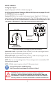
RS-232 / RS‑485 Digital Input Signal To use the RS-232 or RS-485 input signal, connect the RS-232 / RS‑485 Output Signal (Pin 5), the RS-232 / RS‑485 Input Signal (Pin 3), and Ground (Pin 8) to your computer serial port as shown below. (See page 30 for details on accessing RS-232 / RS‑485 input.
OUTPUT SIGNALS RS-232 / RS-485 Digital Output Signal To use the RS-232 or RS-485 output signal, it is necessary to connect the RS-232 / RS-485 Output Signal (Pin 5), the RS-232 / RS-485 Input Signal (Pin 3), and Ground (Pin 8) to your computer serial port as shown on page 8. (See page 30 for details on accessing RS-232 / RS-485 output.) Standard Voltage (0-5 Vdc) Output Signal MC-Series flow controllers equipped with a 0-5 Vdc (optional 0-10 Vdc) will have this output signal available on Pin 6.
CAUTION! D� ��� ������� ���� ������ �� “���� �������’” �������, �� ���� ���� ������� �������� �� ��� ��������� ��� ���� ��� ��������. I� ��� ���� ��������� ���� �������� ���� ������� �������, ������ ��� � ������ �������� ��� � �������� ����� ������.
Information for Alicat TFT (Color Display) Instruments Alicat TFT (color display) instruments have a high contrast back-lit LCD display. TFT instruments operate in accordance with Alicat standard operating instructions for our monochrome menus and displays with the following differences. Multi-Color Display Color Codes: GREEN: Green labels identify the parameters and/or adjustments associated with the button directly above or below the label.
DISPLAYS AND MENUS The device screen defaults to Main display as soon as power is applied to the controller. Main #C +21.50 PSIA +13.60 +0.00 SETPT 0.000 SCCM Air +0.00 SCCM +0.00 CCM MENU The Main display shows pressure, temperature, set‑point, volumetric flow and mass flow. Pressing the button adjacent to a parameter will make that parameter the primary display unit. By hitting the MENU button at the bottom right of the screen you will enter the Select Menu display.
MAIN This mode defaults on power up, with mass flow as the primary displayed parameter. SETPT #C PSIA The following parameters are displayed in +0.00 +21.50 +13.60 the Main mode. SCCM Gas Absolute Pressure: This sensor Air references hard vacuum and reads incoming pressure both above and below local atmospheric pressure. This parameter +0.00 +0.00 is moved to the primary display by pushing SCCM CCM MENU the button above PSIA.
Mass Flow Rate: The mass flow rate is the volumetric flow rate corrected to a standard temperature and pressure (typically 14.696 psia and 25 °C). This parameter is located in the lower middle of the display. It can be moved to the primary display by pushing the button below SCCM in this example. Your display may show a different unit of measure preceded by the letter S. To get an accurate volumetric or mass flow rate, the gas being measured must be selected. See Gas Select, page 21.
SELECT MENU From Select Menu you can change the selected gas, interact with your RS‑232 / RS-485 settings, read manufacturer’s data and access the control setup and miscellaneous screens. Press the button next to the desired operation to bring that function to the screen.
CONTROL SETUP Control Setup is accessed by pressing the button below Control Setup on the Select Menu display. From this screen you can select your set-point source, choose a loop variable and adjust the PID terms. Press BACK to return to the Select Menu display. Press MAIN to return to the MAIN display SETPT LOOP SETPT SETPT SOURCE – Pressing the button VAR +0.0 SOURCE above SETPT SOURCE will allow you to select how the set point will be conveyed to your controller.
CAUTION! N���� ����� � C��������� ���� � ���-���� ���-����� �� �� �������� �� ��������� �� ���� ����. T�� ���������� ���� ����� ���� ����� �� ��� ����� �� �� ������� �� ����� ��� ���-�����. W��� ����� �� �� ����, ���� ��� ���� ��� ����� ���� HOT! CONTROL SETUP (continued) SETPT SOURCE LOOP VAR SETPT +0.0 ON AUTO PID MAIN LN-DN LN-UP >Mass Flow Volumetric Flow Pressure CANCEL SET LOOP VAR—The selection of what variable to close the loop on is a feature unique to Alicat mass flow controllers.
PID TUNING SETPT SOURCE LOOP VAR SETPT +0.0 ON AUTO PID MAIN LN-UP > PD PID PD2I PID LN-DN CANCEL SET P 00100 I 00000 D 02501 BACK LOOP TYPE MAIN PID Values determine the performance and operation of your proportional control valve. These terms dictate control speed, control stability, overshoot and oscillation. All units leave the factory with a generic tuning designed to handle most applications.
The PD algorithm is the PID algorithm used on most Alicat controllers. It is divided into two segments: The first compares the process value to the set-point to generate a proportional error. The proportional error is multiplied by the ‘P’ gain, with the result added to the output drive register. The second operates on the present process value minus the process value during the immediately previous evaluation cycle.
GAS SELECT Gas Select is accessed by pressing the button below GAS SELECT on the Select Menu display. LN-UP C2H6 H2 He >N2 N2O Ne LN-DN MODE Ethane Hydrogen Helium Nitrogen Nitrous Oxide Neon CANCEL To select a gas, use the LN‑UP and LN-DN buttons to position the arrow in front of the desired gas. Press MODE and then PG-UP or PG-DN to view a new page in the gas list. SET Press SET to record your selection and return to the MAIN display. The selected gas will be displayed on the screen.
COMMUNICATION SELECT Access Communication Select by pressing the button above RS232 COMM or RS485 COMM on the Select Menu display. UNIT ID A BAUD 19200 BACK MAIN UNIT ID C UP DN C BACK RESET A SET BAUD DN UP Unit ID – Valid unit identifiers are the letters A-Z and @. The identifier allows you to assign a unique address to each device so that multiple units can be connected to a single RS‑232 or RS‑485 computer port. Press UNIT ID. Use the UP and DOWN buttons to change the Unit ID.
MISCELLANEOUS Miscellaneous is accessed by pressing the MISC button on the Select Menu display. Next select either MISC1 or MISC2. MISC1 will display as shown at left. ZERO BAND refers to Display Zero Deadband. Zero deadband is a value below which the display PRESS ZERO FLOW AVG BAND AVG jumps to zero. This deadband is often desired to prevent electrical noise from showing up on the display as minor flows or pressures that do not exist.
DIAG TEST STP BACK MAIN MISC2 will display as shown at left. STP refers to the functions that allow your selection of standard temperature and pressure conditions. This feature is generally useful for comparison purposes to other devices or systems using different STP parameters. The STP menu is comprised of the STP TEMP and STP PRESS screens. STP TEMP allows you to select from seven standard temperature protocols. The arrow position will automatically default to the currently stored value.
SCROLL R8: AP Sig R9: Temp Sig R10: DP Side R11: DP Brdg R13: AP Brdg R16: Meter Fun R18: Power Up BACK 7871 39071 9986 36673 36673 199 32768 MAIN DIAG TEST: This diagnostic screen displays the initial register values configured by the factory, which is useful for noting factory settings prior to making any changes. It is also helpful for troubleshooting with Alicat customer service personnel. Select the DIAG TEST button from the MISC2 screen to view a list of select register values.
MCV Controller Operating Notes Alicat’s MCV mass flow controller is equipped with an integrated Swagelok® positive shutoff valve. The normally closed valve is air actuated and will remain closed until it is connected to an air source supplying between 60 and 120 psig of air pressure. Once the appropriate amount of air pressure is supplied to the shutoff valve, it will open, allowing flow through the mass controller. Air pressure must be removed from the shutoff valve in order for the valve to close.
MCD Dual Valve Mass Controller Operating Notes The MCD is a versatile Dual-Valve Mass Flow and Pressure Controller. It can be used to: • Measure mass flow and volumetric flow in both directions, plus absolute pressure and temperature; • Control mass or volumetric flow from a pressurized source or to vacuum; • Control absolute pressure or back-pressure in a flowing process; • Control absolute pressure in a closed volume with automatic venting. Application examples are shown below and on the following page.
Inverse Mass Flow (or Volumetric Flow)Control with Vacuum Vacuum Source FLOW Process Bidirectional Mass Flow (or Volumetric Flow)Control Vacuum Source FLOW Gas Source Process FLOW Flowing Absolute Pressure Control Vacuum Source Back-Pressure Control Gas Source Process Positive Pressure Control Dead-Ended Absolute Pressure Control Atmosphere or Vacuum FLOW Closed Process Gas Source FLOW 29
RS-232 / RS-485 Output and Input Configuring HyperTerminal®: 1. Open your HyperTerminal® RS-232 / RS-485 terminal program (installed under the “Accessories” menu on all Microsoft Windows® operating systems). 2. Select “Properties” from the file menu. 3. Click on the “Configure” button under the “Connect To” tab.
Unless otherwise specified each unit is shipped with a default address of capital A. Other valid addresses are B thru Z. Once you have established communication with the unit and have a stream of information filling your screen: 1. Type *@=A followed by “Enter” (or using the RS-232 / RS-485 communication select menu, select A as identifier and exit the screen) to stop the streaming mode of information.
To adjust the Proportional and Differential (P&D) terms via RS-232 / RS-485: Type *@=A followed by “Enter” to stop the streaming mode of information. To adjust the “P” or proportional term of the PID controller, type *R21 followed by “Enter”. The computer will respond by reading the current value for register 21 between 0-65535. It is good practice to write this value down so you can return to the factory settings if necessary. Enter the value you wish to try by writing the new value to register 21.
Gas Select – The selected gas can be changed via RS-232 / RS-485 input. To change the selected gas, enter the following commands: In Polling Mode: Address$$# (e.g. B$$#) Where # is the number of the gas selected from the table below.
Collecting Data: The RS-232 / RS-485 output updates to the screen many times per second. Very short-term events can be captured simply by disconnecting (there are two telephone symbol icons at the top of the HyperTerminal® screen for disconnecting and connecting) immediately after the event in question. The scroll bar can be driven up to the event and all of the data associated with the event can be selected, copied, and pasted into Microsoft® Excel® or other spreadsheet program as described below.
Data Format: The data stream on the screen represents the flow parameters of the main mode in the units shown on the display.
Sending a Simple Script File to HyperTerminal® It is sometimes desirable to capture data for an extended period of time. Standard streaming mode information is useful for short term events, however, when capturing data for an extended period of time, the amount of data and thus the file size can become too large very quickly. Without any special programming skills, the user can use HyperTerminal® and a text editing program such as Microsoft® Word® to capture text at user defined intervals. 1.
would enter 30000 into the box. If you want a line every 5 minutes, you would enter 300000 into the box. 15. When you have entered the value you want, click on OK and OK in the Properties dialog box. 16. Go the Transfer menu and select “Send Text File…” (NOT Send File…). 17. Browse and select the text “script” file you created. 18. Click Open. 19.
Gas Number Short Form 0 1 2 3 4 5 6 7 8 9 10 11 12 13 14 15 16 17 18 19 20 21 22 23 24 25 26 Air Ar CH4 CO CO2 C2H6 H2 He N2 N2O Ne O2 C3H8 n-C4H10 C2H2 C2H4 i-C4H10 Kr Xe SF6 C-25 C-10 C-8 C-2 C-75 A-75 A-25 27 A1025 28 Star29 29 P-5 Long Form Air Argon Methane Carbon Monoxide Carbon Dioxide Ethane Hydrogen Helium Nitrogen Nitrous Oxide Neon Oxygen Propane normal-Butane Acetylene Ethylene iso-Butane Krypton Xenon Sulfur Hexafluoride 75% Argon / 25% CO2 90% Argon / 10% CO2 92% Argon / 8% CO2 98% A
Gas Number Short Form Long Form 0 1 2 3 4 5 6 7 8 9 10 11 12 13 14 15 16 17 18 19 20 21 Air Ar CH4 CO CO2 C2H6 H2 He N2 N2O Ne O2 C3H8 n-C4H10 C2H2 C2H4 i-C4H10 Kr Xe SF6 C-25 C-10 Air Argon Methane Carbon Monoxide Carbon Dioxide Ethane Hydrogen Helium Nitrogen Nitrous Oxide Neon Oxygen Propane normal-Butane Acetylene Ethylene iso-Butane Krypton Xenon Sulfur Hexafluoride 75% Argon / 25% CO2 90% Argon / 10% CO2 Viscosity* 0 deg C 14.696 psia 172.588 209.566 103.657 165.130 137.129 86.127 83.970 186.
TROUBLESHOOTING Display does not come on or is weak. Check power and ground connections. Please reference the technical specifications (pages 50 - 70) to assure you have the proper power for your model. Flow reading is approximately fixed either near zero or near full scale regardless of actual line flow. Differential pressure sensor may be damaged. A common cause of this problem is instantaneous application of high‑pressure gas as from a snap acting solenoid valve upstream of the meter.
Meter does not agree with another meter I have in line. Volumetric meters are affected by pressure drops. Volumetric flow meters should not be compared to mass flow meters. Mass flow meters can be compared against one another provided there are no leaks between the two meters and they are set to the same standard temperature and pressure. Both meters must also be calibrated (or set) for the gas being measured.
Maintenance and Recalibration General: MC-Series Flow Controllers require minimal maintenance. They have no moving parts. The single most important thing that affects the life and accuracy of these devices is the quality of the gas being measured. The controller is designed to measure CLEAN, DRY, NON-CORROSIVE gases. Moisture, oil and other contaminants can affect the laminar flow elements.
Option: Totalizing Mode - Controllers Controllers can be purchased with the Totalizing Mode option. This option adds an additional mode screen that displays the total flow (normally in the units of the main flow screen) that has passed through the device since the last time the totalizer was cleared. The Totalizing Mode screen is accessed by pushing the TOTAL button on the MAIN display.
BATCH PROCESSING MODE – CONTROLLERS ONLY Batch mode is a function within the optional Totalizing mode. Batch mode is designed to provide repeatable, finite flow quantities. DOWN UP SELECT DIGIT 00123.45 ˄ BACK/ CANCEL CLEAR SET To activate Batch Mode: Press BATCH. Then use SELECT DIGIT to move the arrow to the desired digit, and the UP and DOWN buttons to change the value. Press CLEAR to return to zero. Press SET to record your value.
Option: Remote Electronics for High Line or Gas Temperatures Some applications involve operating temperatures outside the standard Alicat device specifications. A solution using remote electronics is available. (This option is not applicable for liquid devices.) The flow body’s components are minimized to only the required sensors. The flow data is sent to the microprocessor electronics up to 6 feet away from the sensor package.
Accessory: BB9 Multi-Drop Box The BB9 Multi-Drop Box makes it convenient to wire multiple flow and/or pressure devices to a single RS-232 or RS-485 port. Now available with a USB interface! The Multi-Drop Box has nine 8 pin mini-DIN ports available. The ports are to be used with a standard double ended 8 pin mini-DIN (DC-62) style cable going from the box to each flow or pressure device.
Accessory: Flow Vision™ SC Software Flow Vision™ SC is an intuitive software interface to help your test cycles run smoother and shorten your engineering time! Flow Vision™ SC lets you connect to and communicate with multiple Alicat units simultaneously. Now you can view virtual displays, control tabs, charts and data lines from every connected Alicat device on the same screen.
Accessories Part Number Description FLOWVISIONSC Flow Vision™ SC software for interface with all Alicat instruments FLOWVISIONMX Flow Vision™ MX software for gas blending BB9 9 position Multi-Drop Box BB9-I 9 position Multi-Drop Box, Industrial connectors PVPS24U Universal 100-240 VAC to 24 Volt DC Power Supply Adapter PS24VHC High current power supply for BB9 use with Large Valve Controllers PCASE Industrial carry and storage case for portable meters/gauges DC-61 8 Pin Male Mini-DIN connec
Accessories MNPT to Compression Fittings Filters & Elements FNPT-MNPT 10-32 - 1/8” SS-200-1-0157 10-32 5μ 510053 10-32 - 1/4” SS-400-1-0256 10-32 20μ 510054 1/8” - 1/8” SS-200-1-2 1/8” 20μ ILF-1/8-20 1/8” - 1/4” SS-400-1-2 1/4” 40μ ILF-1/4-40 1/8” - 3/8” SS-600-1-2 1/2” 40μ ILF-1/2-40* 1/8” - 1/2” SS-810-1-2 3/4” 40μ ILF-3/4-40* 1/8” - 3mm SS-3M0-1-2 20μ element ILFE20 1/8” - 4mm SS-4M0-1-2 40μ element ILFE40 1/8” - 6mm SS-6M0-1-2 40μ element ILFE40L* 1/8” - 8mm SS-8M0
Technical Data for Alicat MC and MCR Mass Flow Controllers 0 to 0.5 sccm Full Scale through 0 to 3000 slpm Full Scale Standard Operating Specifications (Contact Alicat for available options) Performance Accuracy at calibration conditions after tare High Accuracy at calibration conditions after tare Repeatability Zero Shift and Span Shift Operating Range / Turndown Ratio Maximum Controllable Flow Rate Typical Response Time MC & MCR Mass Flow Controller ± (0.8% of Reading + 0.2% of Full Scale) ± (0.
0.5 sccm to 50 sccm approximate shipping weight: 1.1 lb. MC-Series: 0 - 0.5 sccm 0 - 1 sccm 0 - 2 sccm 0 - 5 sccm 0 - 10 sccm 0 - 20 sccm 0 - 50 sccm 100 sccm to 20 slpm approximate weight: 1.
MCR-Series: 0 - 50 slpm 0 - 100 slpm MCR 50 slpm to 100 slpm approximate weight: 9.0 lb.
MCR-Series: 0 - 500 slpm 0 - 1000 slpm 0 - 1500 slpm MCR 1500 slpm approximate weight: 9.0 lb.
MCR-Series: 0 - 3000 slpm MCR 3000 slpm approximate weight: 12.0 lb.
Technical Data for Whisper Low Pressure Drop Mass Flow Controllers 0 to 0.5 sccm Full Scale through 0 to 500 slpm Full Scale Standard Specifications (Contact Alicat for available options.) Performance Accuracy at calibration conditions after tare High Accuracy at calibration conditions after tare Repeatability Whisper MCW & MCRW Mass Flow Controller ± (0.8% of Reading + 0.2% of Full Scale) ± (0.4% of Reading + 0.
MCW 0.5 sccm to 20 sccm approximate shipping weight: 1.1 lb. WHISPER MCW: 0 - 0.5 sccm 0 - 1 sccm 0 - 2 sccm 0 - 5 sccm 0 - 10 sccm 0 - 20 sccm MCW 50 sccm to 2 slpm approximate weight: 1.
WHISPER MCRW: 0 - 5 slpm 0 - 10 slpm 0 - 20 slpm MCRW 5 slpm to 20 slpm approximate weight: 6.4 lb.
WHISPER MCRW: 0 - 50 slpm 0 - 100 slpm 0 - 250 slpm MCRW 50 slpm to 250 slpm approximate weight: 9.0 lb.
Technical Data for MCV & MCVS Mass Flow Controllers 0 to 0.5 sccm Full Scale through 0 to 20 slpm Full Scale The Alicat MCV mass flow controller is designed for applications that require tight shut-off such as vacuum coating and sputtering processes. An integrated pneumatic shut-off valve is normally closed and provides positive shut-off of 1 x 10⁻⁹ atm scc/sec Helium max. MCVS controllers are for use with aggressive gases. Standard Specifications (Contact Alicat for available options.
MCV-Series All ranges MCV approximate weight: 3.0 lb. MCVS-Series All ranges MCVS approximate weight: 3.2 lb.
Technical Data for MCP Moderate Flow Mass Flow Controllers 0 to 50 slpm Full Scale through 0 to 250 slpm Full Scale Alicat MCP mass flow controllers are fitted with a high performance valve for low pressure applications. The following specifications are applicable to Alicat MCP-Series Mass Flow Controllers only. Please Note Maximum Pressure of 80 psig.
MCP-Series: 50 slpm 100 slpm 10 slpm to 50 slpm approximate shipping weight: 3.0 lb. MCP-Series: 250 slpm 100 slpm to 250 slpm approximate shipping weight: 4.4 lb.
Technical Data for Alicat MCD and MCRD Dual Valve Mass Flow Controllers 0 to 0.5 sccm Full Scale through 0 to 3000 slpm Full Scale Standard Operating Specifications (Contact Alicat for available options) Performance Accuracy for Bidirectional Controllers at calibration conditions after tare Repeatability MCD Mass Flow Controller ± 0.2% Full Scale Zero Shift and Span Shift 0.02% Full Scale / ºCelsius / Atm Operating Range / Turndown Ratio 0.
MCD-Series 0 - 20 slpm shown MCRD-Series 0 - 2000 slpm shown
Technical Data for Alicat MCS and MCRS-Series Mass Flow Controllers Alicat MCS and MCRS instruments are built for use with aggressive gases. For the most part, these instruments maintain the specifications of equivalently ranged MC and MCR-Series devices.
MCS-Series: 0 – 0.5 sccm 0 – 1 sccm 0 – 2 sccm 0 – 5 sccm 0 – 10 sccm 0 – 20 sccm 0 – 50 sccm 0.5 sccm to 50 sccm approximate shipping weight: 1.1 lb. MCS-Series: 0 – 100 sccm 0 – 200 sccm 0 – 500 sccm 0 – 1 slpm 0 – 2 slpm 0 – 5 slpm 0 – 10 slpm 0 – 20 slpm 100 sccm to 20 slpm approximate weight: 1.
MCRS-Series: 0 – 50 slpm 0 – 100 slpm MCRS 50 slpm to 100 slpm approximate weight: 9.0 lb.
MCRS-Series: 0 – 500 slpm 0 – 1000 slpm 0 – 1500 slpm MCRS 500 slpm to 1500 slpm approximate weight: 9.0 lb. MCRS-Series: 0 – 2000 slpm MCRS 2000 slpm approximate weight: 12.0 lb.
MCRS-Series: 0 – 3000 slpm MCRS 3000 slpm approximate weight: 12.0 lb.
Technical Data for PROFIBUS Meters, Gauges and Controllers NOTICE: The following specifications are applicable to Alicat PROFIBUS enabled meters, gauges and controllers only. All other operating specifications are shown in the Technical Data page for standard Alicat instruments. All standard device features and functions are available and operate in accordance with the standard Alicat Scientific device operating manual provided with the device.
Eight Pin Mini-DIN Connector Pin-Outs If your Alicat Instrument was ordered with the standard Eight Pin Mini-DIN connection, please be sure to reference the following pin-out diagram. 1 3 2 4 6 7 5 8 Standard 8 Pin Mini-DIN Pin-Out Mini-DIN cable color Black Pin Function 1 Inactive (or optional 4-20mA Primary Output Signal) Static 5.
Locking Industrial Connector Pin-Outs If your Alicat Instrument was ordered with a Six Pin Locking Industrial connection, please be sure to reference the following pin-out diagram. 6 5 1 1 5 6 4 2 3 2 Male Connector: Cable Pin 1 2 3 4 Description Rev. No.
If your instrument was ordered with a DB9 connection, be sure to check the Calibration Label on the device and reference the appropriate pin-out diagram. Standard DB9 Pin-out The following pin-out chart describes the safest and generally compatible arrangement when connecting a non-Alicat DB9 wire to a DB9 equipped Alicat. Not all features may be available between brands, but the common denominators are featured in our DB9 offerings, along with some options for customization.
If your instrument was ordered with a DB9 connection, be sure to check the Calibration Label on the device and reference the appropriate pin-out diagram. DB9A Pin-out The following pin-out chart describes the safest and generally compatible arrangement when connecting a non-Alicat DB9 wire to a DB9A equipped Alicat. Not all features may be available between brands, but the common denominators are featured in our DB9N offerings, along with some options for customization.
If your instrument was ordered with a DB9 connection, be sure to check the Calibration Label on the device and reference the appropriate pin-out diagram. DB9N Pin-out The following pin-out chart describes the safest and generally compatible arrangement when connecting a non-Alicat DB9 wire to a DB9N equipped Alicat. Not all features may be available between brands, but the common denominators are featured in our DB9N offerings, along with some options for customization.
If your instrument was ordered with a DB9 connection, be sure to check the Calibration Label on the device and reference the appropriate pin-out diagram. DB9R Pin-out The following pin-out chart describes the safest and generally compatible arrangement when connecting a non-Alicat DB9 wire to a DB9R equipped Alicat. Not all features may be available between brands, but the common denominators are featured in our DB9R offerings, along with some options for customization.
If your instrument was ordered with a DB9 connection, be sure to check the Calibration Label on the device and reference the appropriate pin-out diagram. DB9T Pin-out The following pin-out chart describes the safest and generally compatible arrangement when connecting a non-Alicat DB9 wire to a DB9T equipped Alicat. Not all features may be available between brands, but the common denominators are featured in our DB9T offerings, along with some options for customization.
If your instrument was ordered with a DB9 connection, be sure to check the Calibration Label on the device and reference the appropriate pin-out diagram. DB9U Pin-out The following pin-out chart describes the safest and generally compatible arrangement when connecting a non-Alicat DB9 wire to a DB9U equipped Alicat. Not all features may be available between brands, but the common denominators are featured in our DB9U offerings, along with some options for customization.
DB15 Pin-Outs If your instrument was ordered with a DB15 connection, be sure to check the Calibration Label on the device and reference the appropriate pin-out diagram. The following pin-out chart describes the safest and generally compatible arrangement when connecting a non-Alicat DB15 wire to a DB15 equipped Alicat. Not all features may be available between brands, but the common denominators are featured in our DB15 offerings, along with some options for customization.
DB15 Pin-Outs If your instrument was ordered with a DB15 connection, be sure to check the Calibration Label on the device and reference the appropriate pin-out diagram. The following pin-out chart describes the safest and generally compatible arrangement when connecting a non-Alicat DB15 wire to a DB15A equipped Alicat. Not all features may be available between brands, but the common denominators are featured in our DB15 offerings, along with some options for customization.
DB15 Pin-Outs If your instrument was ordered with a DB15 connection, be sure to check the Calibration Label on the device and reference the appropriate pin-out diagram. The following pin-out chart describes the safest and generally compatible arrangement when connecting a non-Alicat DB15 wire to a DB15B equipped Alicat. Not all features may be available between brands, but the common denominators are featured in our DB15 offerings, along with some options for customization.
DB15 Pin-Outs If your instrument was ordered with a DB15 connection, be sure to check the Calibration Label on the device and reference the appropriate pin-out diagram. The following pin-out chart describes the safest and generally compatible arrangement when connecting a non-Alicat DB15 wire to a DB15K equipped Alicat. Not all features may be available between brands, but the common denominators are featured in our DB15 offerings, along with some options for customization.
DB15 Pin-Outs If your instrument was ordered with a DB15 connection, be sure to check the Calibration Label on the device and reference the appropriate pin-out diagram. The following pin-out chart describes the safest and generally compatible arrangement when connecting a non-Alicat DB15 wire to a DB15H equipped Alicat. Not all features may be available between brands, but the common denominators are featured in our DB15 offerings, along with some options for customization.
DB15 Pin-Outs If your instrument was ordered with a DB15 connection, be sure to check the Calibration Label on the device and reference the appropriate pin-out diagram. The following pin-out chart describes the safest and generally compatible arrangement when connecting a non-Alicat DB15 wire to a DB15S equipped Alicat. Not all features may be available between brands, but the common denominators are featured in our DB15 offerings, along with some options for customization.
Additional Information for Alicat CSA and ATEX Approved Devices See the following page for Special Conditions regarding the use of these units! II 3 G EEx nA IIC T4 Class I, Div. 2 Group A, B, C and D T4 24 Vdc, 0.800A max Class I, Zone 2 AEx nA IIC T4 WARNINGS: EXPLOSION HAZARD – DO NOT DISCONNECT WHILE CIRCUIT IS LIVE UNLESS AREA IS KNOWN TO BE NON-HAZARDOUS. EXPLOSION HAZARD – SUBSTITUTION OF COMPONENTS MAY IMPAIR SUITABILITY FOR CLASS I, DIVISION 2.
USE of Alicat instruments (M, MW, MS, MC, MCW, MCS, MCR, MCRW, MCRS, P, PS, PC, PCS, PCR and PCRS product families only) in Class 1 Division 2 applications. CSA certifies the use of this product for general use as well as use in hazardous locations as defined by Class 1 Division 2 Group A, B, C and D T4. CSA certification is indicated by the product label as shown below and not by the statements in this, or any accompanying documentation.
Serial Number: ______________________ Model Number: _________________________ Notice: Alicat Scientific, Inc. reserves the right to make any changes and improvements to the products described in this manual at any time and without notice. This manual is copyrighted. This document may not, in whole or in part, be copied, reproduced, translated, or converted to any electronic medium or machine readable form, for commercial purposes, without prior written consent from the copyright holder.
Gas SLPM 100.00 = SLPM 100.00 = SLPM 1.00 = SLPM 1.00 = 3.5316 211.9093 61.0128 3660.7688 SCFM SCFH SCIM SCIH Absolute Density ** Compressibility Viscosity* 25°C 25°C 25°C 14.696 psia 14.696 psia 184.918 1.1840 0.9997 225.593 1.6339 0.9994 111.852 0.6569 0.9982 176.473 1.1453 0.9997 149.332 1.8080 0.9949 93.540 1.2385 0.9924 89.153 0.08235 1.0006 198.457 0.16353 1.0005 178.120 1.1453 0.9998 148.456 1.8088 0.9946 311.149 0.8246 1.0005 204.591 1.3088 0.9994 81.458 1.8316 0.9841 74.052 2.4494 0.9699 104.