
User guide
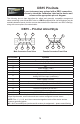
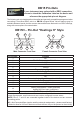

DB15S – Pin-Out “Sierra” Style
Pin Number Function
1 Ground
2 Primary Analog Signal Output
3 N/C
4 N/C
5 Ground
6 N/C
7 N/C
8
Analog Tare (meters — when grounded)
Analog Set-Point Input (controllers)
9 Power Supply Common
10 Ground
11 Secondary Analog Signal Output / xed 5.12Vdc *
12 RS-232 RX (receive) or RS-485 – *
13 Power Supply (+Vdc)
14 RS-232 TX (send) or RS-485 + *
15 Ground
Check your device’s calibration certi cate and user manual for the actual electrical input/
output requirements, as all instruments are custom con gured to some extent.
NOTE: Pins 1, 5, 9, 10 and 15 are connected together inside of the device and are common
grounding points.
N/C = Not Connected/Open (can be used for custom pin assignments – please consult factory).
* Added to allow for full use of features on Alicat devices, may not be present on host wiring.
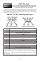
Male Connector Front View Female Connector Front View
11
14
13
12
2
9
11
14
13
9
2
8
8
12
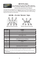
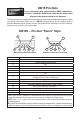
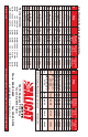
The following pin-out chart describes the safest and generally compatible arrangement when
connecting a non-Alicat DB15 wire to a DB15S equipped Alicat. Not all features may be
available between brands, but the common denominators are featured in our DB15 offerings,
along with some options for customization.
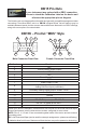
DB15 Pin-Outs
If your instrument was ordered with a DB15 connection,
be sure to check the Calibration Label on the device and
reference the appropriate pin-out diagram.