Operating Bulletin PROFIBUS Innovative Flow and Pressure Solutions 1
Notice: Alicat Scientific, Inc. reserves the right to make any changes and improvements to the products described in this manual at any time and without notice. This manual is copyrighted. This document may not, in whole or in part, be copied, reproduced, translated, or converted to any electronic medium or machine readable form, for commercial purposes, without prior written consent from the copyright holder.
1.1 PROFIBUS Alicat units can be optionally configured with a PROFIBUS communication interface. PROFIBUS communications are done with telegrams. The following is presented to an audience that is informed on the details of the PROFIBUS specification. Details about connections and specifications are found in the standard Alicat Operating Manual and on pages 10-11 of this bulletin. 1 GSD Configuration File The latest GSD file can be downloaded from the Alicat website (www. alicatscientific.
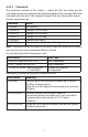
.1 Wait Parameterization After baud rate detection, or if PROFIBUS communications have been stopped and restarted, the unit will be in wait parameterization state. Items that are parameterized are gas select and error mode for the totalizer (if totalizer equipped). 4.1.1 Gas Select The default gas select in the GSD file is “keep current.” This particular gas select tells the unit not to change the gas select that the unit had the last time it was powered up.
At power up, if a user does a configuration read before sending a configuration as is the case when auto configuring the network, this default configuration will be sent. If during operation, after the unit has been configured, the unit is queried for its configuration it will send the current configuration. If a power cycle occurs the unit will return to the default configuration until it is again configured. 4.
Once a unit is tuned to the current process input pressures, a run time configuration would be used that did not include the PID variable as they take up system bandwidth. 4.3.2 Data Out Telegram (From Master) The data out telegram from the master can be configured to contain any combination of Set-point, Control Register, and Command. 4.3.2.1 Set-point The format for a set-point is a 4 byte IEEE 32 big endian floating point number.
4.3.2.3 Command The command consists of four octets — where the first two octets are the command and last two octets are the data that applies to the command. Both the command and data are 16 bit unsigned integers that are in big endian format.
4.4 Diagnostic The PROFIBUS unit will send a diagnostic telegram if an over range condition is encountered. A diagnostic telegram with extended diagnostics will be output. Following the standard six octet header will be two octets. The first is the number of the extended diagnostic octets (0x02). The second octet will be a copy of the status byte that is in the reading and has the same interpretation.
5.3 Unit Commands Unit commands are commands that go directly to the meter/controller and include all commands that an Alicat meter/controller will normally respond to. It is important to note that when the PROFIBUS interface is in Data Exchange mode, the unit acts as is if it were in a streaming mode and does not output data frames to the RS-232 port. Because the meter/controller is in streaming mode, unit commands must be in the format for a streaming meter/controller.
Technical Data for PROFIBUS Meters, Gauges and Controllers NOTICE: The following specifications are applicable to Alicat PROFIBUS enabled meters, gauges and controllers only. All other operating specifications are shown in the Technical Data for standard Alicat instruments. All standard device features and functions are available and operate in accordance with the Alicat operating manual provided with the device.
PROFIBUS Pin-Outs If your Alicat Instrument was ordered with a PROFIBUS connection, please be sure to reference the following pin-out diagram. Power and Signal Connections: Connect to the device using two DB9 connectors. The female top connection is PROFIBUS. The male connection on the side is power and RS-232 or RS-485. Pin out diagrams for all PROFIBUS enabled Alicat devices are shown below. TOP SIDE 5 9 1 6 1. NC 2. OPT GND 3. DP 4. RTS 1 5. DGD 6 6. VP 7. OPT 7 to 30VDC 8. DN 9. NC 5 9 1. NC 2.
Gas SLPM 100.00 = SLPM 100.00 = SLPM 1.00 = SLPM 1.00 = 3.5316 211.9093 61.0128 3660.7688 SCFM SCFH SCIM SCIH Absolute Density ** Compressibility 25°C Viscosity* 25°C 25°C 14.696PSIA 14.696PSIA 184.918 1.1840 0.9997 225.593 1.6339 0.9994 111.852 0.6569 0.9982 176.473 1.1453 0.9997 149.332 1.8080 0.9949 93.540 1.2385 0.9924 89.153 0.08235 1.0006 198.457 0.16353 1.0005 178.120 1.1453 0.9998 148.456 1.8088 0.9946 311.149 0.8246 1.0005 204.591 1.3088 0.9994 81.458 1.8316 0.9841 74.052 2.4494 0.9699 104.