
User Manual


CHAPTER 1 INTRODUCTION
ALR-F800 HARDWARE SETUP GUIDE
DOC. CONTROL #8102141-000 REV A
5
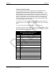
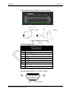
I/O Port Terminal Interface
The ALR-F800 I/O port provides four digital inputs and eight digital outputs,
optically isolated from the reader circuitry for use in noisy industrial
environments. Opto-isolators have two basic elements: a light source (usually a
light emitting diode) and a photo-sensitive detector. These two elements are
positioned facing one another and inserted in an electrical circuit to form an opto-
coupler. The key property of an opto-coupler is that there is an insulating gap
between the light source and the detector. No current passes through this gap,
only the desired light waves representing data. Thus the two sides of the circuit
are electrically isolated from one another.
This protects the circuitry inside the reader from damaging ground loops (when
the external device is at a different ground potential than the reader), and voltage
spikes.
The external device must supply the V+ and V- voltage references.
Alternatively if isolation is NOT required an internal 12V power source is supplied
and can be routed to the V+ and V- pins with a jumper wire. This is only available
if the unit is powered by the DC source jack.
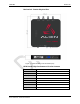
I/O Port Screw Terminal Connector
(Phoenix 14-pin header)
Pin 1 V+ (5-24 VDC External)
Pin 2 V- (Return External)
Pin 3 Output 0 (1.5A max; 7.3A total)
Pin 4 Output 1 "
Pin 5 Output 2 "
Pin 6 Output 3 "
Pin 7 Output 4 "
Pin 8 Output 5 "
Pin 9 Output 6 "
Pin 10 Output 7 "
Pin 11 Input 0 (5-24 VDC)
Pin 12 Input 1 "
Pin 13 Input 2 "
Pin 14 Input 3 "
Pin 15 Internal Fused 12.0 VDC
Pin 16 Chassis GND