
User Manual
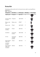
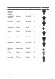
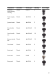
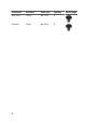
Table Of Contents
- Alienware Area-51 R5 Service Manual
- Before working inside your computer
- After working inside your computer
- Technical overview
- Lifting the computer
- Removing the stability foot
- Replacing the stability foot
- Removing the side panels
- Replacing the side panels
- Removing the battery
- Replacing the battery
- Removing the battery case
- Replacing the battery case
- Removing the hard drive
- Replacing the hard drive
- Removing the U.2 fan
- Replacing the U.2 fan
- Removing the right AlienFX side-panel connector
- Replacing the right AlienFX side-panel connector
- Removing the left AlienFX side-panel connector
- Replacing the left AlienFX side-panel connector
- Removing the I/O board
- Replacing the I/O board
- Removing the drive-bay heat sensor cable
- Replacing the drive-bay heat sensor cable
- Removing the memory modules
- Replacing the memory modules
- Removing the graphics card
- Replacing the graphics card
- Removing multiple graphics cards
- Replacing multiple graphics cards
- Removing the wireless card
- Replacing the wireless card
- Removing the coin-cell battery
- Replacing the coin-cell battery
- Removing the top fan
- Replacing the top fan
- Removing the logo board
- Replacing the logo board
- Removing the solid-state drive
- Replacing the solid-state drive
- Removing the PCI fan
- Replacing the PCI fan
- Removing the front-bezel heat sensor cable
- Replacing the front-bezel heat-sensor cable
- Removing the processor liquid-cooling assembly
- Replacing the processor liquid-cooling assembly
- Removing the processor
- Replacing the processor
- Removing the power-supply unit
- Replacing the power-supply unit
- Removing the system board
- Replacing the system board
- Removing the handle bars
- Replacing the handle bars
- Removing the front bezel
- Replacing the front bezel
- Removing the rear bezel
- Replacing the rear bezel
- Removing the base panel
- Replacing the base panel
- Removing the top tron-lighting cable
- Replacing the top tron-lighting cable
- Removing the bottom tron-lighting cable
- Replacing the bottom tron-lighting cable
- Removing the antenna cables
- Replacing the antenna cables
- Downloading drivers
- BIOS setup program
- Troubleshooting
- Getting help and contacting Alienware
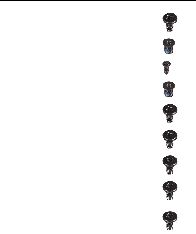
Screw list
The following table provides the list of screws that are used for securing dierent
components.
Table 1. Screw list
Component Secured to Screw type Quantity Screw image
Stability foot Computer #6-32x6 2
Security-cable
slot latch
Computer #6-32x5.2 1
Battery-case
door
Battery case M2x5.7 1
Battery case Chassis #6-32x5.2 2
Hard-drive
assembly
Chassis #6-32x6 1
Hard drive Hard-drive
bracket
#6-32x3.6 4
U.2 fan Hard-drive
assembly
bracket
#6-32x6 2
Right AlienFX
side-panel
connector
assembly
Chassis #6-32x6 2
Right AlienFX
side-panel
connector
Bracket #6-32x6 1
15