
User Manual
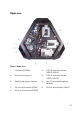
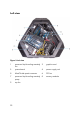
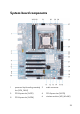
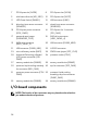
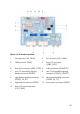
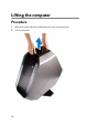
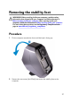
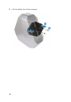
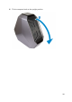
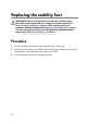
Table Of Contents
- Alienware Area-51 R5 Service Manual
- Before working inside your computer
- After working inside your computer
- Technical overview
- Lifting the computer
- Removing the stability foot
- Replacing the stability foot
- Removing the side panels
- Replacing the side panels
- Removing the battery
- Replacing the battery
- Removing the battery case
- Replacing the battery case
- Removing the hard drive
- Replacing the hard drive
- Removing the U.2 fan
- Replacing the U.2 fan
- Removing the right AlienFX side-panel connector
- Replacing the right AlienFX side-panel connector
- Removing the left AlienFX side-panel connector
- Replacing the left AlienFX side-panel connector
- Removing the I/O board
- Replacing the I/O board
- Removing the drive-bay heat sensor cable
- Replacing the drive-bay heat sensor cable
- Removing the memory modules
- Replacing the memory modules
- Removing the graphics card
- Replacing the graphics card
- Removing multiple graphics cards
- Replacing multiple graphics cards
- Removing the wireless card
- Replacing the wireless card
- Removing the coin-cell battery
- Replacing the coin-cell battery
- Removing the top fan
- Replacing the top fan
- Removing the logo board
- Replacing the logo board
- Removing the solid-state drive
- Replacing the solid-state drive
- Removing the PCI fan
- Replacing the PCI fan
- Removing the front-bezel heat sensor cable
- Replacing the front-bezel heat-sensor cable
- Removing the processor liquid-cooling assembly
- Replacing the processor liquid-cooling assembly
- Removing the processor
- Replacing the processor
- Removing the power-supply unit
- Replacing the power-supply unit
- Removing the system board
- Replacing the system board
- Removing the handle bars
- Replacing the handle bars
- Removing the front bezel
- Replacing the front bezel
- Removing the rear bezel
- Replacing the rear bezel
- Removing the base panel
- Replacing the base panel
- Removing the top tron-lighting cable
- Replacing the top tron-lighting cable
- Removing the bottom tron-lighting cable
- Replacing the bottom tron-lighting cable
- Removing the antenna cables
- Replacing the antenna cables
- Downloading drivers
- BIOS setup program
- Troubleshooting
- Getting help and contacting Alienware

7 PCI-Express slot (SLOT5) 8 PCI-Express slot (SLOT6)
9 solid-state drive slot (M2_SSD1)
10 PCI-Express slot (SLOT7)
11 LED Power Switch (PANEL1) 12 USB connector (USB1)
13 drive-bay heat-sensor connector
(SENSOR1)
14 chassis heat-sensor connector
(SENSOR2)
15 PCI-Express power connector
(PCIE_PWR1)
16 PCI-Express fan 1 connector
(PCI_FAN1)
17 password reset jumper
(PASSWORD_CLR1)
18 SATA drive connector
(HDD_SATA3_4)
19 SATA drive connector
(HDD_SATA1_2)
20 USB connector (FUSB3_MB2)
21 USB connector (FUSB3_MB1) 22 U.2 SSD connector
23 coin-cell battery socket (BAT1)
24 CMOS reset jumper (RTC_CLR1)
25 Advanced Technology xTended
(ATX) power connector (ATX
PWR1)
26 processor socket (CPU1)
27 memory-module slot (DIMM2) 28 memory-module slot (DIMM1)
29 processor liquid-cooling assembly
fan connector (MID_FAN1)
30 top fan connector (TOP_FAN1)
31 processor-power connector (CPU
PWR1)
32 processor liquid-cooling
assembly pump-fan connector
(PUMP_FAN1)
33 memory-module slot (DIMM3) 34 memory-module slot (DIMM4)
I/O-board components
NOTE: The location of the connectors may vary based on the selections
you made at the time of purchase.
24