
User Manual
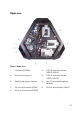
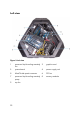
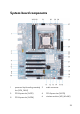
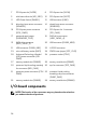
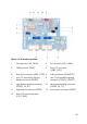
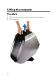
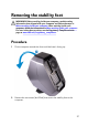
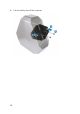
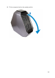
Table Of Contents
- Alienware Area-51 R5 Service Manual
- Before working inside your computer
- After working inside your computer
- Technical overview
- Lifting the computer
- Removing the stability foot
- Replacing the stability foot
- Removing the side panels
- Replacing the side panels
- Removing the battery
- Replacing the battery
- Removing the battery case
- Replacing the battery case
- Removing the hard drive
- Replacing the hard drive
- Removing the U.2 fan
- Replacing the U.2 fan
- Removing the right AlienFX side-panel connector
- Replacing the right AlienFX side-panel connector
- Removing the left AlienFX side-panel connector
- Replacing the left AlienFX side-panel connector
- Removing the I/O board
- Replacing the I/O board
- Removing the drive-bay heat sensor cable
- Replacing the drive-bay heat sensor cable
- Removing the memory modules
- Replacing the memory modules
- Removing the graphics card
- Replacing the graphics card
- Removing multiple graphics cards
- Replacing multiple graphics cards
- Removing the wireless card
- Replacing the wireless card
- Removing the coin-cell battery
- Replacing the coin-cell battery
- Removing the top fan
- Replacing the top fan
- Removing the logo board
- Replacing the logo board
- Removing the solid-state drive
- Replacing the solid-state drive
- Removing the PCI fan
- Replacing the PCI fan
- Removing the front-bezel heat sensor cable
- Replacing the front-bezel heat-sensor cable
- Removing the processor liquid-cooling assembly
- Replacing the processor liquid-cooling assembly
- Removing the processor
- Replacing the processor
- Removing the power-supply unit
- Replacing the power-supply unit
- Removing the system board
- Replacing the system board
- Removing the handle bars
- Replacing the handle bars
- Removing the front bezel
- Replacing the front bezel
- Removing the rear bezel
- Replacing the rear bezel
- Removing the base panel
- Replacing the base panel
- Removing the top tron-lighting cable
- Replacing the top tron-lighting cable
- Removing the bottom tron-lighting cable
- Replacing the bottom tron-lighting cable
- Removing the antenna cables
- Replacing the antenna cables
- Downloading drivers
- BIOS setup program
- Troubleshooting
- Getting help and contacting Alienware
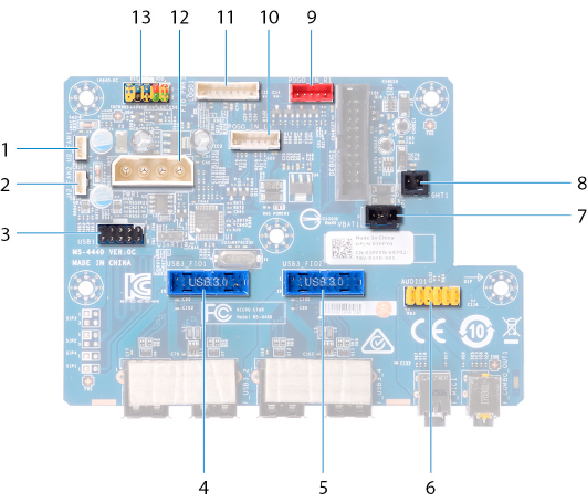
Figure 3. I/O-board components
1 Fan connector (U2_FAN1) 2 Fan connector (U2_FAN2)
3 USB connector (USB1) 4 front I/O connector
(USB3_FIO1)
5 front I/O connector (USB3_FIO2) 6 audio connector (AUDIOIO1)
7 rear I/O accessibility lighting
battery connector (VBAT1)
8 rear I/O accessibility lighting
connector (PORCH_LIGHT1)
9 right theater-lighting connector
(POGO_IN_R1)
10 left theater-lighting connector
(POGO_IN_L1)
11 logo board connector (LOGO1) 12 main-power connector (PWR1)
13 front I/O control connector
(FIO_PWR1)
25