
Technical data
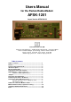

AFSK1201 Seite 4
Test pin MP2 "MODEM RX": Generate a test signal with a alternating 1200 / 2200 Hz tone (frequency al-
ternates every 1/600 second). You may use a TNC2 in TAPR mode and start the CAL command in diddle-
mode. Adjust the signal at MP2 to a 1:1 ratio (HI:LO) by carefullt tuning trimmer P3 (3105).
Connecting the radio to AFSK1201
Use a standard 5 pin (180°) DIN-connector. The pins are assigned as follows:
pin 1: MIC Microphone of the radio, audio output of TNC
pin 2: GND Ground
pin 3: PTT Push-to-talk contact, switched to ground to transmit
pin 4: SPK AF-output of the radio (loudspeaker)
pin 5: not connected
Attention: the five pins are not enumerated in turn! The numbers of the contacts are printed on the black
insulating body of the plug (almost invisible figures) and on the rear panel of the TNC3/31. The pins are ar-
ranged in the following order: 3 (PTT), 5 (n.c.), 2 (GND), 4 (DEM), 1 (MOD). The middle pin 2 (GND) is made
as a soldering tag for attaching the screen wires of a microphone cable.
MIC (pin 1)
This is the AF output of the modem which is connected directly to the microphone input of the radio. You can
adjust the voltage from approx. 10 mV to 300 mV according to the sensitivity of the microphone input of the
radio.
The input impedance of the microphone input should be 10 kΩ or more. The output is decoupled (DC-free)
by a 0.1 µF ceramic capacitor. This is important when the modem is to be used with handheld radios using
the same wire for PTT and microphone.
SPK (pin 4)
This is the AF input of the modem, connected directly to the speaker output of the radio. The audio signal
should be 0,1 V
ss
or more (35 mV eff.). At a 8 Ω speaker this sounds 'quite weak'. More amplitude is OK,
turn the volume control to 1/4 or 'normal volume' for packet radio use with the AFSK1201.
Do not apply more than 6 volt (this is 'very loud' volume)', however you won't damage the modem as the
input is protected by two diodes. The SPK-input of AFSK1201 is coupled with a capacitor (DC-free).
PTT (pin 3)
This pin is switched to ground when the modem is set to transmit mode. All radios use a switch to ground to
key the transmitter (exception: some German police-radios). A N-channel VMOS-field effekt transistor, with a
switching capability of 25 Volt and 200 mA is used.
The 'ON' resistance of the FET is only few Ohms, the leakage current less than 1 µA.
For transceivers with other PTT circuits use an additional switching amplifier and a reed-relay with protection
diode parallel to the coil.
Many (handheld) transceivers use the same wire for PTT switch and microphone. The dc signal for the PTT
is decoupled by a capacitor. In series with the PTT-switch, there is a resistor (2 to 20 kΩ) so that the audio
signal from the microphone isn't short circuited. When pressing the PTT-key, the direct current can flow
through this resistor, keying the transmitter.
To connect such radios, you can simply connect pin 1 and pin 3 of the 5 pin DIN connector at the modem by
a approx. 4.7 kOhm miniature resistor. The common MIC and PTT wire is soldered to pin 1 of the DIN con-
nector. Do not install the resistor inside of the TNC (at the modem board) because the resistor might cause
problems when the modem is to be used with other radios.
GND (pin 2)
Ground of the radio
Spare (pin 5)
This pin is not connected.