44/430MHz DUAL BAND FM TRANSCEIVER DJ-V57 Instruction Manual Thank you for purchasing your new Alinco transceiver. Please read this manual carefully before using the product to ensure full performance, and keep this manual for future reference as it contains information on after-sales service. In case addendum or errata sheets are included with this product, please read those materials and keep them together with this instruction manual for future reference. ALINCO, INC.
NOTICE / Compliance Information Statement NOTICE / Compliance Information Statement This equipment has been tested and found to comply with the limits for a Class B digital device, pursuant to part 15 of the FCC Rules. These limits are designed to provide reasonable protection against harmful interference in a residential installation.
NOTICE / Compliance Information Statement Conformity Information Alinco, Inc.
Contents Contents NOTICE / Compliance Information Statement ................................................2 Contents .............................................................................................................4 Warning...............................................................................................................7 Introduction ......................................................................................................12 Before transmitting........................
Contents 4.7 Call-Channel Mode.............................................................................................31 4.8 Receiving ............................................................................................................31 4.8.1 Monitor Function........................................................................................32 4.9 Transmitting........................................................................................................32 4.9.
Contents 8.Set Mode........................................................................................................45 8.1 Set Mode Operation ............................................................................................45 8.2 Entering the Set Mode ........................................................................................45 8.3 Available Parameters ..........................................................................................46 8.3.
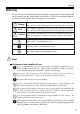
Warning Warning To prevent any hazard during operation of Alincon's radio product, in this manual and on the product you may find symbols shown below. Please read and understand the meanings of these symbols before starting to use the product. d Danger d Alert d Caution d a m This symbol is intended to alert the user to an immediate danger that may cause loss of life and property if the user disregards the warning.
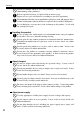
Warning j and/or damage to the product(s). Risk of explosion if battery is replaced with an incorrect type. a Dispose of, or recycle used batteries according to your local regulations. The manufacturer declines any responsibilities against loss of life and property due to a a failure of this product when used with or as a part of a device made by third parties. Use of third party accessory may result in damage to this product. It will void a our warranty for repair.
Warning j Do not handle a power supply with a wet hand. It may result in electric shock. Securely plug the power supply to the wall outlet. Insecure installation may a result in short-circuiting, electronic shock and/or fire. Do not plug the power supply into the wall socket if the contacts are dirty. j Short-circuit and/or overheating may result in fire, electric shock and/or damage to the product. j fire, electric shock and/or damage to the product.
Warning d Caution ■ Environment and condition of use Do not use the product in proximity to a TV or a radio. It may cause interference or receive interference. j Do not install in a humid, dusty or insufficiently ventilated place. It may result j in electric shock, fire and/or malfunction. Do not install in an unstable or vibrating position. It may result in electric j shock, fire and/or malfunction when/if the product falls to the ground.
Warning Lightning Any person is not safe outdoor during thunderstorm and lightning. This condition is getting worse if somebody keeps a hand-held radio; chances of being hit by lightning are doubled since lightning may hit a radio antenna as well. At this time, there is no handheld radio having any kind of protection against lightning current (which is higher than 10 kA.). Note also that no car provides adequate protection of its passengers or drivers against lightning as well.
Introduction / Before transmitting Introduction Thank you very much for purchasing this excellent Alinco transceiver. Our products are ranked among the finest in the world. This radio has been manufactured with state of the art technology and it has been tested carefully at our factory. It is designed to operate to your satisfaction for many years under normal use. PLEASE READ THIS MANUAL COMPLETELY TO LEARN ALL THE FUNCTIONS THE PRODUCT OFFERS.
1.Features 1. Features This transceiver has the following main features. 1 144/430MHz dual-band handheld transceiver Choice of 3 power output levels (5/2/0.
2.Accessories 2. Accessories 2.1 Installations 2 2.1.1 Antenna ■ Attaching the Antenna 1. Hold the antenna by its base. 2. Align the grooves at the base of the antenna with the protrusions on the antenna connector. 3. Slide the antenna down and turn it clockwise until it stops. 4. Confirm that the antenna is securely connected. ■ Removing the Antenna Turn the antenna counter-clockwise to disconnect the antenna. 2.1.2 Hand Strap Attach the hand strap as shown. There are two ways to attach it.
2.Accessories 2.1.4 Battery Pack For the specifications and the charging procedures, please refer to "Battery Packs"(page 59) and "Using the Chargers"(page 60). ■ Attaching the Battery Pack Align the catches on the battery pack with the grooves on the unit, and close the latch until it clicks. 2 Catch Latch Groove ■ Removing the Battery Pack Push the latch in the direction of the arrow, and pull out the battery pack.
2.Accessories Caution 2 16 • Risk of explosion, generation of heat or leak of chemicals inside if the battery is replaced by an incorrect type. Use always the recommended types of batteries in this manual only. • The battery pack isn't fully charged when shipped. It must be charged before use. • Charging should be conducted in a temperature range of 0ºC to +40ºC (+32ºF to +104ºF). • Don't modify, dismantle, incinerate or immerse the battery pack in the water as this can be dangerous.
2.Accessories ■ Charging the Battery Pack Using DC-Jack on the Unit The unit can charge the EBP-65 and EBP-66 optional Ni-MH battery packs by supplying DC power through the DC-jack on the unit using EDC-146/147/148 wall chargers or an optional DC power supply (DC 12V~DC 16V, 1A or more: IEC/EN 60950-1 compliant) and a DC cable such as EDC-37. 2 1. Attach the battery pack by referring to "Battery Pack" (page 15). 2.
2.Accessories 2.1.5 Prevent Short Circuiting the Battery Pack Be extra cautious when carrying the rechargeable battery pack; short circuiting will produce surge current possibly resulting in fire. 2 DON'T carry with metals of any type, e.g. chains. DON'T carry the battery pack inside bags made of conductive materials. Do enclose inside a non-conductive enclosure. (bags or handkerchief made only of non-conductive material) DON'T place in the proximity of metals or conductives, e.g. nails, chains.
3.Names and Operations of Parts 3. Names and Operations of Parts 3.1 Names and Operations of Keys and Ports ■ Top and Front 3 Rotate the dial to select the frequency of operation, memory channel, offset frequency, tone frequency, DCS code, Set mode settings, and the characters for name-tags. Rotating the dial while pressing the FUNC key increases or decreases the frequency in 1MHz order. Microphone/Spe For an optional speaker/Mic connection.
3.Names and Operations of Parts ■ Side 3 Antenna side SMA Antenna Connector FUNC key PTT key MONI key DC-IN jack 20 Dial side Attach the whip antenna. If you plan to use an optional antenna, select one that is tuned to the operating frequency. The FUNC key is used in combination with the other keys to access the various functions of the unit. To enter the Set mode to set operating parameters, press the FUNC key continuously for about 2 seconds. Press the PTT key to transmit, release to receive.
3.Names and Operations of Parts 3.2 Keypad 3 key Without pressing the FUNC key. While appears after the FUNC key is pressed. Inputs 1. Channel step setting (page 26). Inputs 2. Offset frequency setting (page 27). Inputs 3. Alert Function (page 43). Inputs 4. Tone Encode / Tone Squelch setting (page 36). Inputs 5. Hi/Mid/Low power setting (page 32). Inputs 6. VOX setting (page 43). Inputs 7. DCS (digital code squelch) setting (page 37). Inputs 8. Auto dialer operation (page 40).
3.Names and Operations of Parts 3.3 Display (LCD) 3 Appears when the FUNC key is pressed. Indicates the shift (+/-) direction. Appears when setting the CTCSS tone encoder. Appears when setting the tone squelch. Appears when setting the VOX. Appears when setting the DCS. Appears when setting the NFM. Displays the frequency and scan operation. Displayed when the frequency or the keypad is locked. Appears when the Repeater-Access function is activated. Appears when Auto-Power-Off function is activated.
4.Basic Operation 4. Basic Operation 4.1 Turning On the Power Hold the key down for a second. To turn off the power, hold the the display turns off. key down until 4.2 Adjusting the Audio Output (Volume) • There are 31 audio output levels (00~30). • The default setting is level 15. There is no audio output at this status. 1. Press the key. The level is displayed on the LCD. 4 2. Rotate the dial to increase or decrease the level. As the setting value increases, the audio becomes louder. 3.
4.Basic Operation 4.4 Operating Modes This DJ-V57 has three operating modes: VFO mode, Memory mode and CALL mode. The VFO mode allows to operate at the displayed frequency. The Memory mode has 200 channels (VHF/UHF mixture) and the CALL mode has one VHF and one UHF channel. 4 ■ Switching Between Modes “VFO mode” and “Memory mode” are switched by pressing the key appears on the display when “Memory mode” is activated, and disappears when “VFO mode” is activated.
4.Basic Operation 4.5 Setting the Frequency in the VFO Mode The factory default of this unit is the VFO mode. The VFO mode allows you to change the frequency and operating parameters by using the dial and key operations. 4.5.1 Setting the Frequency ■ To Select the VFO Mode The key switches between the VFO and Memory mode each time the key is pressed. " " is displayed on the LCD when the unit is in the Memory mode.
4.Basic Operation Tuning step 5.0kHz 10.0kHz 12.5kHz 15.0kHz 20kHz 25kHz 30kHz Entry completion digit Final digit selection 1kHz Accept 0 or 5 as valid number. Accept any of 0 to 9 keys. 10kHz 10kHz When you input the 10kHz digit, the 1kHz digit is set automatically as follows. 0---00.0, 1---12.5, 2---25.0, 3---37.5, 4---invalid, 5---50.0, 6---62.5, 7---75.0, 8---87.5, 9---invalid Auto-complete after the 10kHz digit entry. 10kHz Auto-complete after the 10kHz digit entry.
4.Basic Operation 4.5.3 Shift Direction and Offset Frequency Settings In conventional repeater systems, a signal received on one frequency is retransmitted on another frequency. The difference between these two frequencies is called the offset frequency. The selectable offset frequency of this unit is from 0 to 99.995MHz. 1. Press the FUNC key, and while is displayed, press the key to display the current offset frequency and shift direction settings. 2.
4.Basic Operation 4.6 Memory Mode This mode allows recalling and operating the preprogrammed frequency or setting in the memory channels. This unit provides up to 200 memory channels, 2 CALL channel (VHF/UHF), 2 Repeater-Access function memory (VHF/UHF), 10 Transmitter Detecting Function memory and 2 Program scan edge memory (VHF/UHF). 4.6.1 How to Program Memory Channel(s) 1. Select a frequency and operating parameters to be programmed in the VFO mode. Programmable parameters are explained later.
4.Basic Operation 4.6.4 Quick Program Memory Channel(s) This function is to quickly write in the memory. 1. Select a frequency and operating parameters to be programmed in the VFO mode. 2. Press the key for more than 2 seconds. 3. The memory number blinks and a beep sounds. NOTE: This function can't be used if all memory channels are already programmed. 4.6.
4.Basic Operation 4.6.6 Programming a Repeater-Access Function Setting The "Repeater-Access" function is to set the desired shift and tone parameters to the current operating frequency by just 2 key-touches. Please set the parameters to be applied to the Repeater-Access function here. 1. Enter the Memory mode (by pressing the key if necessary). 2. Rotate the dial to select MrpV-SET (VHF band) or MrpU-SET (UHF band). 3.
4.Basic Operation 4.7 Call-Channel Mode This mode is used to recall a most frequently used memory channel (stored in MC channel) with a single key-touch. 1. Press the key. " " is displayed on the LCD, and the channel programmed in MC is recalled. 2. Press the key again or the key in the Call mode to return to original operating mode (VFO/memory). ■ How to Program Call-Channel Mode 1. Select the Memory mode by pressing the key. 4 2. Rotate the dial to select the MC channel. 3.
4.Basic Operation 4.8.1 Monitor Function In case the receiving signal is weak and the audio is intermittently cut off by the squelch, press the MONI key. As long as this key is pressed, the squelch including TSQ/DCS unmutes making the audio easier to hear. • The squelch is unmuted while the MONI key is pressed, regardless of the squelch level setting. • This function unmutes the squelch even if the DCS and Tone Squelch functions are set. 4.9 Transmitting 4 1.
5.Useful Functions 5. Useful Functions 5.1 Scan Modes The scan function automatically searches the receiving signals. There are 2 modes for scan-resume condition. • Busy Scan: The scan stops when a signal is detected, stays until the signal is gone then resumes scanning. • Timer Scan: The scan stops when a signal is detected, and resumes scanning after 5 seconds regardless of receiving status (TIMER1 setting). During scanning, the 1MHz decimal point ( ) on the frequency display flashes.
5.Useful Functions 5.1.3 Setting Skip Channels You can select the memory channels that you wish to skip during the memory-scan. • Press the FUNC key in the Memory mode, and while is displayed, press the key to set the currently selected memory channel as a skip channel. Use the same procedure to clear the skip channel setting. • The 10MHz decimal point appears for memory channels that are set as skip channels. NOTE: The Call channel and Repeater-Access memory are automatically skipped during scanning.
5.Useful Functions 5.4 Naming Memory Channels In the Memory mode, it is possible to display up to 7 alphanumeric characters (Nametag) instead of conventional frequency display. 5.4.1 Setting Name-Tag 1. Select the memory channel. 2. Press the FUNC key, and while is displayed press the key. 3. [A ] flashes on the display. 4. Rotate the dial to select a character to be the first digit. 5. Press the flashing. key to input the next character. The previous character will stop 6.
6.Selective Calling 6. Selective Calling ■ Selective Calling Operations • To communicate only with selected stations, use either the Tone Squelch or the DCS function. The Tone Squelch function unmutes the squelch only when a signal added with one of the matching 39 CTCSS tone frequencies is received. • The DCS function unmutes the squelch only when a signal added with one of matching 104 digital codes is received. • It isn't possible to use the Tone Squelch and DCS functions at the same time. 6.
6.Selective Calling 6.1.2 Switching Off the Tone Squelch Press the key in Tone Squelch Setting mode to select TCS-OF, then press any key other than the MONI key to complete the setting. 6.1.3 To Differentiate the ENC/EDC Tones It is possible to set the encode and decode tones independently in the Tone Squelch Setting mode. • To set the encode tone, when displayed, select a desired tone. The decode tone is set automatically to the same tone.
6.Selective Calling 6.2.2 Changing the DCS Code 1. Rotate the dial in DCS Code Setting mode (while " " is displayed). 2. Press any key other than the MONI key to complete the setting. • The same DCS code is set for ENC/DEC, differential setting isn't available. One of the following 104 DCS codes can be selected.
6.Selective Calling ■ Advantage of DET It enables DCS squelch operation even in poorer signal conditions. ■ Disadvantage of DET When it is activated, suppose 2 stations are sharing the same channel and using the DCS selective-calling technique and transmitting at the same time. After station A with its corresponding DCS is gone, you may still hear station B even his DCS code is different from A, although he can't open your DCS squelch by his signal alone. 6.
6.Selective Calling 6.4 Auto Dialer The DTMF tones can be stored in the memory to automatically transmit. 6.4.1 Setting the Auto Dialer • All 16 DTMF tones up to 16 characters are available for each of 9 memories and "M st" memory called an Auto Dialer memory. ■ Programming the Auto Dialer Memories 1. Press the FUNC key, and while is displayed on the LCD, press the key to enter the Dialer Setting mode. The "M1" appears.
6.Selective Calling 6.4.3 Redial (While Receiving) This function generates the last DTMF tones used by the unit. 1. Press the FUNC key, and while is displayed on the LCD, press the key. 2. Press the key. The last DTMF tones (either the auto dialer code or a manually input DTMF code) is automatically generated from the speaker. The unit doesn't transmit the tones in this operation. 3. To transmit, press the FUNC key while pressing the PTT key, then the key.
7.Special Functions 7. Special Functions 7.1 Repeater-Access 1. In the VFO/Memory/Call channel mode, select the channel to which you wish to apply the Repeater-Access setting. 2. Press the FUNC key, and while is displayed on the LCD, press the The Repeater-Access setting is applied to the operating frequency. key. NOTE: Preset parameters on the Repeater-Access function memory will be effective at any frequency.
7.Special Functions 7.3 VOX This function allows to transmit without using the PTT by simply speaking into the microphone. When you have stopped speaking, the unit will return to receive. 1. Press the FUNC key and while is displayed on the LCD, press the key to display the VOX setting. 2. Rotate the dial to select the using microphone. VO-OFF VO-IN VO-OUT VO-OFF : VOX function OFF VO-IN : Internal mic VO-OUT : Option mic 3. Adjust the VOX sensitivity level. Press the key. 4.
7.Special Functions 7.5 Battery Type Setting Select the correct battery type from Ni-MH battery pack, Li-ion battery pack and Alkaline dry cells in order to display the battery-level icon correctly and to perform the battery-charge using the DC-jack. 1. Press the key for more than 2 seconds. 2. Rotate the dial to select battery type.
8.Set Mode 8. Set Mode The Set mode is used to customize the various operational parameters of your DJ-V57. 8.1 Set Mode Operation This chart shows the available parameters in the Set mode.
8.Set Mode 8.3 Available Parameters 8.3.1 Menu 1 Battery Save (BS) Function This function prevents useless battery consumption by switching the power ON/OFF at a fixed ratio if there is no key operation or receiving signal for a continuous period of 5 seconds or more. 1. BS-1 is displayed on the LCD. 2. Rotate the dial to select BS-1, BS-2 or OFF. BS-1 saves the more amount of battery but may cause slight delay on receiving. BS-2 allows smoother communication but saves the less amount of battery.
8.Set Mode 8.3.5 Menu 5 Auto-Power-Off Setting This function prevents the batteries from being exhausted when you forget to switch off the power. 1. APO-OF is displayed on the LCD. 2. The auto power off setting will change between ON and OFF when the dial is turned. 3. When the setting is set to ON, is displayed on the LCD. APO-OF APO-ON ■ APO Operation After having activated the APO and about 30 minutes elapse without any key-operation, the unit turns off automatically alerting with a beep sound.
8.Set Mode 8.3.8 Menu 8 Clock Shift Setting In the unlikely event that you may hear a weak noise always on the same frequency, it may be so-called a CPU-clock noise. Unfortunately this is due to the circuit-design of this product and can't be eliminated, but can be moved away to another frequency. 1. SFT-OF is displayed on the LCD. 2. Rotate the dial to select the clock shift setting on and off. SFT-OF SFT-ON NOTE: This function isn't a noise-blanker.
8.Set Mode 8.3.10 Menu 10 Tone-Burst Frequency Setting 1. 1750 is displayed on the LCD. 2. Rotate the dial to select the tone-burst frequency. 1750 2100 1000 1450 (unit: Hz) 8.3.11 Menu 11 Time Out Timer (TOT) Setting This function stops the transmission automatically when the continuous transmission time exceeds the set time. 1. T-OFF is displayed on the LCD. 2. Rotate the dial to change the TOT time. TOT time can be set to a maximum of 450 sec. OFF 30 60 90 ----- 450 (unit: seconds) 8.3.
8.Set Mode NOTE: The following 4 menus explain the Auto Dialer DTMF tone parameters. Please refer to the chart at the end for details. 8.3.13 Menu 13 DTMF WAIT Time Use this parameter to delay the time to start transmitting the DTMF tones in Auto Dialer operation. The initial setting is 100ms. 1. DWT-01 is displayed on the LCD. 2. Rotate the dial to change the DTMF wait time setting. DWT-01 ----- DWT-05 ----- DWT-10 (unit: 100ms) 8.3.
8.Set Mode The DTMF Timing Chart PTT ON WAIT Time DTMF code First Digit Pause Burst Time Time DTMF code DTMF code Burst Time Burst Time Pause Time 8.3.17 Menu17 Stand-by Beep/DTMF Setting By activating this function, a short beep or DTMF tone code sounds to indicate that your transmission is end. 1. STB-OF is displayed on the LCD. 2. Rotate the dial to switch the display as shown below. STB-OF STB-BE STB-DT • STB-BE Short beep sounds to indicate that your transmission is end.
8.Set Mode 8.3.18 Menu18 Mid power RF output of the mid power can be customized. Variable range is from 1 to 3W approximately. Default setting: About 2W (05) 1. MID-05 is displayed on the LCD. 2. Rotate the dial to select the power level. 3. Press PTT to transmit.You can still very the setting in this state. Press any key other than PTT or FUNC to complete the setting and return to the operating mode.
9.Cloning and Packet Operation 9. Cloning and Packet Operation 9.1 Cloning The memory data and customized operational parameters can be transferred from a Master unit to other DJ-V57 (Slave units). 9.1.1 Cable Connection • Make sure that both units are turned off before connecting the cable. • Connect the Microphone/Speaker jack on the Master unit with the Slave unit using an optional clone cable (EDS-11) as shown below, then turn on both units.
9.Cloning and Packet Operation 9.1.3 Master Unit Operation 1. In the Clone mode, press the PTT key of the master unit. "SD***" is displayed on the LCD, and starts the data-transfer. 2. After the transfer is completed successfully, "PASS" is displayed. 3. Turn off the unit. Repeat the same sequence to clone more units. Stop moving the SD***, COMERR etc. on the display means that the cloning is failed. Please read below and repeat the procedure. 9.1.4 Slave Unit Operation 1.
9.Cloning and Packet Operation 9.2 Packet Operation Packet operation is one of the data communication methods, which enables data transmission and reception with a personal computer through an optional TNC unit available from third-parties. 9.2.1 Packet Operation Connections Connect the packet communication TNC (Terminal Node Controller) terminals to the SP (Ø3.5 mm plug) and MIC (Ø2.5 mm plug ) connectors on the top of the transceiver.
10.Maintenance and Reference 10. Maintenance and Reference 10.1 Troubleshooting Please check the list below before concluding that the unit needs to be serviced. If a problem persists, please reset the unit. The setting/CPU program-related troubles are often resolved by the reset. 10 56 Action Possible Cause Symptom Check that the battery pack terminals are Nothing appears on Poor battery pack clean, and pack is correctly attached. connection. the display when turning on the power. Battery is exhausted.
10.Maintenance and Reference 10.2 Resetting 10.2.1 All Resetting When you reset the unit, all settings are returned to the initial factory settings. The reset deletes the programmed memory channels also. 1. Turn on the unit with the FUNC and keys pressed together. 2. All the icons appear on the display. Release the keys. All display will disappear for 2 seconds, and then reappear. The initial mode is the VFO. NOTE: THE ALL RESET DELETES ALL THE MEMOORIES.
10.Maintenance and Reference 10.3 Options EBP-63/64 Li-ion Battery Pack (DC 7.4V 1100mAh / 1600mAh) EBP-65/66 Ni-MH Battery Pack (DC 7.
10.Maintenance and Reference • When using EDC-36, EDC-37, EDC-43, EDC-146, EDC-147, connect them to the unit first before turning on the unit. • EBP-63, 64, 65 and 66 are IPX7-grade water-proof only when correctly attached and used with DJ-V57. 10.3.1 Microphone/Speaker Cable (EDS-14) 1. Turn off the unit. 2. Turn the plug clockwise until it stops. Check to be sure it is securely connected. 3. Connect the Microphone/Speaker plugs to the each jack. Plug Speaker jack (φ3.5) Microphone jack (φ2.5) 10.3.
10.Maintenance and Reference 10.3.3 Using the Chargers Caution Please also read the "Warning" (page 7 of this manual) and the safety instruction that is included in the accessories' package before operating for your safety. ■ Charging with the EDC-143 (Trickle Charger) Please make sure that following items are included in the package.
10.Maintenance and Reference 3. Press the sides of the adjustment plate, and attach it to the proper grooves of the basket according to the size of the battery pack. Make sure that the characters A, B and C on both sides of the stand match each other and the plate is placed all the way down to the bottom.
10.Maintenance and Reference Specifications *The charging time may vary depending on the condition of the battery pack and the temperature of the environment. NOTE: Refer to page 64 for information about how to charge the battery using addtional baskets.
10.Maintenance and Reference 3. Press the sides of the adjustment plate, and attach it to the proper grooves of the basket according to the size of the battery pack. Make sure that the characters A, B and C on both sides of the stand match each other and the plate is placed all the way down to the bottom.
10.Maintenance and Reference Specifications *The charging time may vary depending on the condition of the battery pack and the temperature of the environment. ■ Connecting Additional Baskets (EDC-143R/144R) In order to use EDC-143R and EDC-144R, an optional power supply (IEC/EN 609501 compliant) of 1A/5A minimum respectively is required. A DC cable isn't included in the package; the suggested DC cable is 20 AWG wire, shorter than 1m (3feet) in length. 1.
10.Maintenance and Reference 4. Attach the connective stay and the insulation sheets to cover the terminals to avoid shortcircuiting. Caution This insulation sheet marked * is provided to all EDC-143/144 series chargers. Please be sure to cover the bottom of the charger with this sheet as shown above to prevent short-circuiting before using them for the first time. 5. Connect the other ends of the DC cable to the output terminals of the power supply. Be mindful to the polarities of the terminals.
10.Maintenance and Reference 10.3.4 Dry Cell Case An EDH-34 is available for operation with using AA cells. Lift up the catches ① on the top of the case to remove the cover. Place 6 AA cells, then close the cover in order of ② then ③ . Be sure that the cover is securely closed. Caution About Handling Dry Cell Case: • This dry cell case isn't water-proof. • Be extra-cautious to the polarity of the cells (+)/(-). Misplacing cells may result in leak, fire or explosion.
11.Specifications 11. Specifications ■ General TX Frequency range (T ver) RX TX Frequency range (E ver) 144.000~147.995MHz 420.000~449.995MHz 144.000~147.995MHz 136.000~173.995MHz 420.000~449.995MHz 400.000~511.995MHz * Guaranteed range per specifications 144.000~145.995MHz 430.000~439.995MHz RX 144.000~145.995MHz 430.000~439.995MHz Modulation F3E(FM) Channel steps 5, 10, 12.
11.Specifications ■ Transmitter Output power High DC13.5V 5W (VHF) EBP-63/65 5W High DC13.5V 5W (UHF) EBP-63/65 4.5W Middle 2W (Initialization) Low 0.5W Modulation Variable reactance frequency modulation Spurious emission -60dB or less Max. deviation ( WFM / NFM ) ±5kHz / ±2.5kHz Mic. impedance 2kΩ ■ Receiver 11 68 Receive system Double conversion superheterodyne Sensitivity (VHF/UHF) *12dB SINAD -14dBu / -12dBu Intermediate frequencies 38.
The following table lists available characters.
Memory Mode Structure
■ Quick manual page 23 Hold the key down for a second. page 23 1. Press the key. 2. Rotate the dial to increase or decrease the level. page 23 1. Press the key. 2. Rotate the dial to increase or decrease the level. page 32 Press the FUNC key, and while is displayed on the LCD, press the key *Changes in order of 0.5W, 2W, and 5W.