UNC-9412/9512 High-Speed Dome Network Camera User Manual Software Version 1.
Contents Contents .........................................................................................................................2 Package Contents ...........................................................................................................4 System Requirements.....................................................................................................6 Introduction...............................................................................................................
Application Setting ......................................................................................................69 Event ...................................................................................................................69 Motion Detection................................................................................................76 Firmware upgrade .............................................................................................77 Factory Default ...................
Package Contents Make sure you have received the following items. If any item is missing, please contact your dealer. Camera unit Pack: 1. Speed dome camera 2. Network module base Accessory Pack: 3. Optical cover 4. Inserting holder 5. Decorative rim 6.
7. Screw Pack Pack A Pack B Pack C Pack D 8. Inserting opening sample sheet 9. Quick Installation Guide 10. Hardware Installation Manual 11.
System Requirements UNC-9412 Network Environment LAN 10/100M Ethernet Monitoring system resource requirements Operating system Browser System hardware Windows 2000 Professional SP4,XP Home SP2 Internet Explorer 6.x or later versions CPU: Pentium 4, 2.
Introduction This product is a speed dome camera that can connect to Ethernet, LAN, and any broadband networks. Unlike traditional CCTV cameras, a CPU and a webpage server are built in the speed dome camera to provide a professional remote monitoring function for the user. This camera provides a 360° quick rotation monitoring and an intelligent image detection system that automatically locks on target and enlarges the image when an abnormal object is detected.
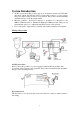
System Introduction 1. AC/DC power inlet: This product supports both alternate current (AC24V/1.0A) and direct current (DC12V/2A). Please connect the product to a power supply. The power input of this product is non-polarized. The product can automatically determine the type of the incoming current. 2. Ethernet connector: An RJ-45 connector is provided for connection to the 10Base-T Ethernet cable or 100 Base-T High Speed Ethernet cable.
LAN socket Please connect the product to your network from the LAN socket. External alarm connector (DI/DO) See Appendix A for details of D1/DO. Default settings After booting up the system, press and hold the button for 5 seconds to reset the product to its default settings.
Hardware Installation Important Safety Precautions 1. 2. 3. 4. 5. Please carefully read the instructions before installation. Keep the manual for future use. Pay attention to all warnings on the equipment and in the manual. Follow all instructions and operation procedures. Turn off the power before wiping the camera. Liquid or cleaner spray is not allowed. 6. Must use the recommended accessories to avoid failure. 7. Use the power supply and voltage as recommended in the manual. 8.
The hardware installation instructions below are intended to provide all required knowledge regarding installation of the camera. As for the setting of the network and the description of the interface, please read the related part of the User's Manual. Notice: Use of the camera must comply with local laws and regulations.
Notice for unpacking Take out the lens protection pad for easier removal of the PTZ Dome Camera from the box. Do not put the equipment on a firm surface, or the protruding metal connector beneath the camera will be damaged. It is recommended to keep the camera in the package box before the installation begins. Take out the items from the accessory pack, but do not remove the outer packaging of the optical cover.
Ceiling Installation Procedure 1. Take the network module base put from the camera unit pack. 2. Use the screws in Screw Pack A to secure the module base on the wooden plate. Note: Do not affix the camera on a ceiling made from fragile material, such as gypsum, calcium carbonate, magnesia, PU, PVC, and glass. The thickness of the wooden plate should be at least 1.5 cm. If the camera is to be fixed on a concrete or brick surface, suitable setscrews should be prepared by the user.
5. Align the arrow on the PTZ Dome Camera with the screw hole on the network module base. 6. Turn the PTZ Dome Camera to the right until both screw holes are aligned. 7. Use the screws in Screw Pack B to secure the camera. 8. Plug the network cable. Connect the video terminal if analog video output is required. 9. Connect the power cable and, if required, the alarm input /output lines and microphone cable. Note: The power input must be 24V AC 2A or 12V DC 2A.
10. Remove the decorative rim from the accessory pack. Cut the edge as shown if it is necessary to pull out wires inside the rim. 11. Mount the decorative rim onto the network module base and notice the position of the outlet hole. 12. Use the screws in Screw Pack D to secure the rim to the base.
13. Remove the lens protection cover. 14. Remove the outer package of the optical cover and align the optical cover with the gap of the PTZ Dome Camera. Close the cover and turn right till secured. Finally, remove the protection film and avoid fingerprints on the cover. Note: While installing, be careful not to scratch or leave fingerprints on the optical cover. Gloves are recommended for installation.
Inserting Installation Procedure 1. Take the opening sample sheet out from the accessory pack and draw a circle on the material according to the opening sample sheet. Use an appropriate tool to open a hole. Note: Do not affix the camera on a ceiling made from fragile material, such as gypsum, calcium carbonate, magnesia, PU, PVC, and glass. The thickness of the wooden plate should be at least 1.5 cm. 2. Take the Push the inserting holders out from the accessory pack and push them into the hole. 3.
5. The adjusting screw determines the height of the PTZ Dome Camera beneath the ceiling. Turn the screw clockwise to extend the camera, or turn the screw counterclockwise to draw back the camera. Note: When the inserting installation method is adopted, the three legs carry the total weight of the camera. Thus, they should be firmly secured to avoid damage to the equipment and personnel. If the surface to which the legs are secured is not level, adjust the adjusting screw of each leg to level the camera.
9. Align the arrow on the PTZ Dome Camera with the screw hole on the network module base. 10. Turn the PTZ Dome Camera to the left until both screw holes are aligned. 11. Use the screw in Screw Pack B to secure the camera. 12. Inserting the assembled PTZ Dome Camera and network module base into the inserting holder slowly from top to the bottom. 13. Align with the three supporting pillars of the inserting holder set. Use the screws in Screw Pack C to secure the camera.
14. Mount the decorative rim onto the network module base and notice the position of the outlet hole. 15. Use the screw in Screw Pack D to secure the rim to the base. 16. Illustration of the completed inserting installation.
17. Plug the network cable. Connect the video terminal if analog video output is required. 18. Connect the power cable and, if required, the alarm input /output lines and microphone cable. 19. Remove the lens protection cover.
20. Remove the outer packaging of the optical cover and align the optical cover with the gap of the PTZ Dome Camera. Put the cover to its position, turn right to the end, and remove the protection film. Do not leave any fingerprints on the cover Note: While installing, be careful not to scratch or leave fingerprints on the optical cover. Gloves are recommended for the installation. Dust may accumulate to the optical cover after prolonged use and affect the image quality.
Camera Settings After the hardware has been installed, insert the supplied CD in the computer and execute the file IP FINDER.EX following the steps below to search for and change the IP address of the camera. 1. Start the machine. Execute the IP Finder.exe from the supplied CD. 2. Find the camera (Search) Search for the product from your LAN. The factory IP setting 192.168.0.20 appears on the screen. 1. Click Search to find the IPCAM on the LAN. 3.
3. Click Submit to validate new settings. 5. Confirmation When all changes have been confirmed, click “Exit” to quit. 4. When all changes have been confirmed, click Exit to quit. Notes: 1. The IP FINDER can only find the IP addresses of cameras that share the same hub on the LAN. For information about finding IP addresses on the Internet, refer to the “DDNS Setting”, or “UpnP Setting”. 2. All UIC camera/network server products can be found and changed using the IP FINDER software. 3.
Camera Setting from a Router You can use DHCP when you want to use the camera on the Intranet (LAN). However, the IP must fixed when you want to use the camera on a WAN. For this application, it is required to set up a virtual server on the ADSL router. Follow the steps below to complete the setting: 1. Enter the camera setting page to set a fixed IP. (Refer to the “Network Setting”.) Ex.: 192.168.0.49 2. Enter the ADSL router main setting page. Ex.: Zonet ADSL router 3.
Change the Internet Explorer Setting This product uses ActiveX Control to play images and sound on your PC. The ActiveX Control application software will be downloaded to your PC when you connect it to the Internet. To ensure successful download of the software, the Internet Explorer "security settings" must be changed accordingly. Make sure that the security level is set to Medium, the commonly used default security level.
Install IE Tab. Restart Firefox. IE Tab online learning.
Enter the Main Page 1. Open the IE browser and key in the IP address of the product. Key in the IP address of the camera When the login screen appears, key in "root" in the User Name and Password fields. Click OK. Camera login screen 2. Key in the default “username” and “password”. Default User Name: root Default Password: root You can access the camera as an administrator by default and set up for other users or privileges from the “Basic Settings” -> “User”. 3.
Click “Install ActiveX Control”. Setup prompt screen 4. The security warning screen appears. Click "Install". The ActiveX Control is named "UIC ActiveX Control". This software is owned by UIC and well certified. You can use it without any doubts about its validity. Click “Install”. 5. If a firewall block window pops up, select Unblock.
6. When installation of the ActiveX control is completed, the image transmitted from the camera and the operation interface appear on the screen.
Camera Main Page Descriptions: Source: Information bar 1. Format: resolution of the current video stream 2. FPS: Frame Per Second of the current video stream 3. BitRate: bandwidth per second of the current video stream 4. Brand Logo – Click for connect to the website of the company Product Video image Source Attention: Please change the streaming setting to HTTP if nothing appears in the image area. Control Panel 1. Pan direction: This function controls the camera to move up, down, left or right.
Control the vertical direction of the camera. Control the horizontal direction of the camera. Set the angle for each movement. 2. Rotation speed: This function controls the speed of rotation in the Preset, Tour, and AutoPan modes. 7 options are available. “1” is the slowest and “7” is the fastest speed.
3. Optical ZOOM: A build-in 18x or 26x optical lens (depending on the camera model) is used for zooming the image. You can directly drag the small ball on the control bar for quick zooming or click the + or - button at both ends of the control bar to zoom precisely. The movement speed of the lens is adjustable. 4. Digital ZOOM: The build-in 12x digital zooming function can enlarge the picture.
to (64 locations). This function can save the location you want to monitor and the camera will automatically rotate to the saved location when you click the number of that location. Precise positioning can be achieved without the need for manual control. 1. Click Set to enter the preset setting window. 2. Enter a name for the location. 3. Rotate the camera to a desired location 4. Click Update and then Exit. 5.
2. Enter a name for the tour setting. Up to 5 groups of tour settings can be defined. 3. Time (second) to stop at each tour location. 4. Select a preset location. 5. Click Update and then Exit. Auto horizontal tour mode. Auto horizontal tour mode. Auto horizontal tour mode. 9. AutoPan: You can use this function to enable or disable the automatic horizontal tour mode. In the AutoPan mode, the camera automatically rotates counterclockwise and keeps horizontally rotating till disabled. 10.
12. Alert: Notification of alarm If the camera detects a movement or an alarm, the Alert button will flash to alert the monitoring personnel. Click the Alert button to stop the flashing. Alarm notification Alert message display is activated. Alert message display area. Enable to save alert messages. 13. Alert Message: Alert Message: The Enable/Disable button can activate or stop the display of the alert message. When Disable is selected, no message will show.
1. 14. Language (interface language selection) This product currently supports 4 languages: English, Simplified Chinese, Traditional Chinese and Japanese. Video area digital zoom-in options Language selection 15. Camera Position: sets the position for display of the image Normal: Normal image (Display on the ceiling; default value) Flip: Upside down image Mirror: left and right opposite image Rotate 180: Mirrored and upside-down(Display on the desktop). Camera position 16.
Digital zoom 17. Streaming: sets the video stream protocol (HTTP is recommended) This product provides three different video streaming protocols: UDP, TCP, and HTTP. HTTP is recommended because it allows the video stream to go through the firewall. (Refer to Setting/Basic Setting/Network/Streaming for more information). UDP: provides the fastest but most unreliable transmission service. Video steams are transmitted through UDP Port (50000~60000 by default) to ensure the fastest image transmission.
Video streaming 18. Brightness: Adjusts the brightness of the image/ Contrast: Adjusts the contrast ratio of the image. In the setting window, pressing the 十 or 一 adjustment button can additionally adjust the brightness or contrast of the image. Pressing 十 will increase the brightness or contrast, while pressing 一 will decrease the brightness or contrast. Adjustment of the brightness and contrast of the image 19.
directory (C:\video). A red mark appears at the bottom left corner of the image when the recording function is running. Snapshot button Recording button 20. Snapshot: When you click this button, a picture of the current image will be saved in the default folder (C:\snapshot). Note: If you are using the Windows Vista operation system, files may not be saved in the default folder when you click the REC or Snapshot button. This is because the Vista system blocks the activity of untrusted websites.
3. Switch to the Security tab. 4. Select Trusted site 5. Click on Sites. 6. Enter the IP address of the speed dome. 7. Cancel the selection of this option. 8. After the input is completed, click on Add. 9. Click on Close after completion. 10. Exit the IE Browser and reopen again. If the setting is correct, Trusted Sites will display. 21. Path: Setting of the path and filename for the recording and snapshot files The default filename is the creation date of the file.
22. Enable/Disable microphone: When you click the speaker icon, a "Forbidden" mark will show on the icon and the sound from an external microphone will not be received. 23. ANS: Anti-Noise System (Default is on. Enabling this function is recommended.) When you click the ANS icon, a "Forbidden" mark will show on the icon and the ANS system is disabled. When the ANS is enabled, noises around the camera, such as the repeating fan noise, will be removed.
System Settings System setting contains basic and application settings. The basic setting is executed for basic system information, transmission speed, audio/video code, user authorization, date/time, and IP filter, while the application setting is executed for event triggering definition and other relevant settings, definition of the motion detection area, firmware update, reset to factory default, and reboot.
Otherwise, it does not activated. OFF: LED is turned off. Flash: LED flashes according t o the user-defined interval. Basic Setting > System > System Log The administrator can view all login information of this camera, including boot record, video streaming mode, login IP, changes, and the date/time information. You can copy the entries to a Word document and save them manually. Please note that all information is deleted when you turn off the machine.
1.Enter multimedia data from the main screen. 2. Select a streaming link 4. Enter the link name. 3. Add a new link. 6. Select OK to save the setting. 45 5. Enter the IP address of the camera, e.g. rtsp://xxx.xxx.xxx.
7. Select this stream name to proceed with linking. 8. Select “Yes” to connect. 10. Loading the image. 9. Connecting. 11. Video stream screen . Basic Setting > Video / Image > Video Image >Video Format You can select MPEG4 or MJPEG as the video format. It is recommended to select MPEG4 for real-time browsing to optimize the bandwidth.
good choice for the best resolution when video recording is required for collection of evidence. Video resolution streaming Basic Setting > Video / Image > Video Image >Video Resolution Generally speaking, selection of resolution is dependent on the bandwidth of the network you are using. This product offers different selections for video/audio settings. However, to ensure undisrupted image transmission, you need a higher uploading bandwidth.
Frame rate selection Basic Setting > Video / Image > Video Image >Frame per Second (FPS): With NTSC, you can choose 1, 2, 3, 4, 5, 6, 7, 10, 15 or 30 for video resolution With PAL, you can choose 1, 2, 3, 4, 5, 6, 12 or 25 for video resolution. FPS selection Basic Setting > Video / Image > Video Image >Video Quality You can select Fix Quality (resolution priority) or Fix Bitrate (fluency priority) at the same bandwidth.
Video quality selection Fix bitrate fastest. 15 transmission speeds ranging from 32K to 4M are available in the Fix Bitrate mode. The higher the transmission speed, the better the quality and fluency Fix bitrate first Select GOP speed GOP provides users with the function to set the pages of the I Frame and P Frame to be transmitted in the MPEG4 mode.
Basic Setting > Video Image > OSD You can set to display the date, camera name and other information on the screen. Basic Setting > Video Image > OSD > Display Mode You can select to display the date (Date), time (Time) or text (Text). Basic Setting > Video Image > OSD > Display Text You can key in the text to be displayed on the screen (Ex.
Basic Setting > Video / Image > Camera Advance Setting Basic Setting > Video / Image > Camera Advance Setting > Setting Window When the setting on this page is changed, a new image will immediately appear on the real-time display window. Real time display window Auto ICR setting Basic Setting > Video / Image > Camera Advance Setting > ICR Setting When the ambient illumination becomes dim, the ICR changes the color filter to the monochrome mode via a micro motor in front of the lens.
Basic Setting > Video / Image > Camera Advance Setting > White balance The white balance setting can adjust the difference of white color in natural or artificial light. Select Auto if you are not familiar with this setting. White Balance Basic Setting > Video / Image > Camera Advance Setting > Exposure Mode The exposure mode defines how the computer processes the natural light source. 5 modes are available: full auto, manual, shutter priority, iris priority, and bright.
Privacy area Masked area Mask color setting Masked area effect The masked area move when the camera change position Basic Setting > Audio (Sound) Basic Setting > Audio > Audio (sound setting) 53
Basic Setting > Audio > Audio > Audio Raw Format You can select No Audio or PCM. When you select No Audio, the sound transmission from the built-in microphone pauses. When you select PCM, the sound transmission resumes. The factory default is PCM. Sound transmission format Pin 1(+)及 2(-) Basic Setting > User(User) The administration of the camera can set up access privileges by administrator, operator, and viewer to ensure the security and control of the camera.
PPPoE setting Streaming UPnP SMTP SAMBA Notification IP Filter setting Event Setting schedule setting event server trigger setting Motion Setting Firmware Upgrade Factory default Reboot Setting PTZ Control v v v v v v v v v v v v root v v v v v v v v User with PTZ privilege Steps: Click Add (to add a new user), Update (to change the privilege or password of a user on the list), or Delete (to delete a user from the list) and complete required fields. Then Click "Save" to complete the setting.
User setting Add a new user and set up a different i il Change the privilege or password of a user. You cannot Delete a user from the list. Log in the username, password and privilege as required. You can also define the PTZ control here. Basic Setting > User > User Setting (privilege setting) For special business situations, this product allows you to log in to browse without the need of keying in your username and password. For this purpose, you need to check “Enable” at Anonymous Login.
Root can not delete but can be update Activate the anonymous view and camera rotation functions; define the number of viewers who are allowed for on-line review simultaneously. Basic Setting > Network (Network Settings) Basic Setting > Network > Network (cable network setting page) Basic Setting > Network > Network > IP Assignment Cable network setting DHCP setting: DHCP(Dynamic Host Configuration Protocol) is a protocol that enables automatic assignment of TCP/IP information to the client.
Other settings: For IP address, Subnet mask, Default gateway, DNS 1, and DNS 2, the DHCP server will assign these values automatically when DHCP is in "ON" status; otherwise, you need to key in the values manually. Note: Where no IP address is assigned from the DHCP server, the system will set the Link-Local Address automatically. Basic Setting > Network > Streaming (streaming Setting) Setting of the video streaming port (HTTP and factory default are recommended) 1.
1. Dial: You can select whether or not to dial when you boot the machine. 2. Use DHCP or fixed IP for connection to the LAN environment. 3. Key in the IP address of the camera and enter "PPPoE Setting" following the route Setting Basic Setting Network PPPoE. 4. Key in the xDSL "Username" and "Password" acquired from your ISP. Click Save to confirm the setting. 5.
successfully. Basic Setting > Network > DDNS (Dynamic Domain Name Server Setting) The IP address (Ex. 210.168.0.22) is like a telephone number, while the website address is like a name in an address book. The DDNS allows the user to access the website by entering the name of the website without memorizing a bunch of cold numbers. When you apply for an Internet service, you will have at least one IP address from your ISP that is either fixed or dynamic.
DDNS setting Basic Setting > Network > UPnP (Universal Plug and Play) If you connect your camera to a router, IP allocator, or wireless AP, your camera will possibly be blocked by the NAT and can’t be located on the Internet. To penetrate the firewall, activate the supportive item- UPnP. The Link URL shows the external IP address and the port of the router. Enter the IP address in the Internet Explorer to penetrate the NAT.
Website link UPnP setting To activate the UPnP function in Windows OS: Ex: Windows XP: 1. Windows component installation. 1. Click Control Panel 2. Click Add/Remove Programs 4. Click Networking Services 5. Click Detail 6. Check UPuP User Interface 3. Click Add/Remove Windows Components 2.
2. Click Exceptions 1. Click Windows Firewall in the Control Panel 3. Check UPnP Configuration. 3. View the connection device using “My Network Place” 1. Open “My Network Place” 2. The LAN camera appears. Double-click to access the main page. Basic Setting > Network > SMTP Server (mail server setting) This camera is able to transmit images to a particular email address when a motion detection event occurs or a sensor is triggered. To use this function, a mail server setting for the camera is required.
User name: the SMTP server username. Password: the password of the SMTP server. Select “SAVE” to save the setting. Basic Setting > Network > Samba This camera is able to upload the snapshots to a specified shared folder when an event is triggered. To use this function, a Samba setting is required. Options: Active: Enable/Disable Samba Authentication: Enable/Disable Username: the username Password: the password Path: specify the IP address of the computer you want to share with and the file name, i.e. 192.
Basic Setting > Network > Notification Of IP Address Change (IP address change notice) This setting is not necessary for a fixed IP. For a dynamic IP, you need to update the IP address every time you connect to the Internet to access the camera. This setting allows you to update the IP address by the automatic notification of IP address change. Choose one of the following three notice options to update the IP address: 1.
Notification of IP change Basic Setting >\ Network >\ Multicast This function allows multiple people to watch video streaming without limitation on the number of users, but is only applicable in the LAN environment. The video streaming format (MPEG4/MJPEG) depends on the selected image format setting in Basic Setting → Video/Image → Video Format.
Basic Setting > Date/Time (date/time setting) 日期/時間設定 Basic Setting > Date/Time > Server Time (the date/time of the server) Basic Setting > Date/Time > PC Time (the date/time of your PC) Basic Setting > Date/Time > Time Setting (date/time setting) There are three ways to synchronize the time. 1. Synchronize the time with PC’s time: The preset method of time synchronization of the camera time with your PC time. 2.
Basic Setting > IP Filter This function filters IP addresses and is able to allow or deny visits from particular addresses/target addresses Ip filter setting Basic Setting > IP Filter > General IP Filtering: enables/disables the IP filter Policy: allows/denies access Basic Setting > IP Filter > Filter IP Address (Overview of the set IPs) Add: enter the IP address you want to allow or deny the access of in the front field.
Application Setting Application Setting > Event (event trigger setting page) This camera is equipped with intelligent security management functions. It ensures security monitoring by allowing user to define “trigger events” based on particular times and situations, and sets the camera respond to the event.
Options: • General: Name: • Name the trigger event here. Response to event trigger: the time setting of the trigger event Always: Always monitoring During time: Check the date you want to monitor (Sun~Sat) and the duration of monitoring here. For example, if you want to set the camera to monitor from 7 pm after work to 7 am next morning from Monday to Friday, check the boxes from Monday to Friday, enter “19:00” in the “Start From” field, and enter “12:00” in the “Duration” field.
Add Schedule: Add Schedule setting page The Add Event setting page and the Add Schedule setting page are basically the same except that the Add Schedule setting page does not have the option “Trigger by” to indicate the sources of the trigger event. Click Save to save and activate your settings when you complete setting. Delete: delete the event cluster setting. Modify: modify the event cluster setting.
Application Setting > Event > Trigger (manual test of trigger response) Whenever the camera detects abnormal events during the scheduled time, it will automatically respond by performing trigger response. There are 3 types of trigger responses: alarm sending, LED status indicator flash, and emailing the alarm or recorded image to the specified server. To use this function, enter the server information by accessing Application Setting > Event > Event Server.
Trigger mail: Sending mail Click “Set” after you enter the email address and subject to test the integrity of the sent mail. Trigger FTP: Sending AVI file to FTP Server Upload AVI files to FTP server to test the file integrity. HTTP Server: Sending message to HTTP Server Upload message to HTTP server to test the message integrity. Enter the message in the “Message” field. You may go to Application Setting > Event > Event Server to make a complete custom parameters settings.
Add ftp server Name: the name of the FTP Network Address: IP address of the FTP Login: Log-in name Password: Log-in password Upload Path: Uploading path Port: Port Passive: Check to set the FTP status as passive Click Add Http to go to the setting page and enter the information of the HTTP server you specified.
Login: Log-in name Password: Log-in password Proxy: Proxy server name Proxy Port: Proxy server port Proxy Login: Proxy server log-in name Proxy Password: Proxy server log-in password Click Add Tcp to go to the setting page and enter the information of the TCP server you specified.
Application Setting > Motion Detection You can open the setting frame by clicking on the area to monitor. To move area to monitor, drag the area with your mouse; to adjust the size of the frame, drag the arrow to adjust after you move the mouse to the edge of the area and left-click; There are 3 frames available for setting. You may adjust the sensitivity of the area by entering the degree of sensitivity in the “Sensitive” field. “1” is least sensitive, ”100” is extremely sensitive.
Application Setting > Firmware upgrade Firmware upgrade Contact your dealer for more information about firmware upgrade. The sales representative will transmit the latest version to you via e-mail. When you receive the firmware, decompress the file (uImage.gz) to your PC and follow the steps below to execute the upgrade. Important! Read Carefully!! 1. Close all active applications on your PC. 2. Select “Firmware Upgrade” The Firmware Upgrade Setting page appears. Select the location 3.
韌體更新中 upgrade. When the firmware upgrade has been completed, the machine reboots automatically. Reconnect to the server after 60 seconds. Note: The new firmware is burned into the Flash ROM during the upgrade, so you must take care during the process and make sure it is not interrupted during the operation. The system may be damaged seriously and need to be returned to the factory for repair if the power cable is removed or becomes loose during the upgrade.
Application Setting > Factory Default You can use this function to reset to factory default, but all changes, including the IP address, you have made are deleted. Back to the default setting Factory Default: Reset to factory default . Warning window Resets all parameters, except the IP parameters: You can use this function to reset to factory default.
Backup: Data backup Back all parameters: Back up all changes you have made. When you click Backup, a file download window appears. Back up the file named param.bin (Attention: Don't change the file name; otherwise, the backup may fail.) Restore backup parameters: You can select this function to restore the changes you have made. To do this, click Browse… to select a backup file and click submit to confirm the restoration.
Attachment A: External Alarm In addition to the motion detection executed by the internal software application, the product can connect to external infrared detectors, beepers, and smoke detectors. For more information about these external devices, contact to your local retailer, dealer or installation service provider. This product provides a standard Alarm I/O for you. This camera provides 4 sets of digital inputs (DIs) and 2 sets of digital outputs (DOs).
Warning! Pin 4 The alarm will be triggered when alarm pin 3 & 4 are formed as a short circuit. Please do not connect the electric voltage or current into alarm input pin because the electronic current might burn the product. Pin 3 Warning! The alarm will be triggered when alarm pin 3 & 5 are formed as a short circuit. Please do not connect the electric voltage or current into alarm input pin because the electronic current might burn the product.
Attachment B: Bandwidth Estimation Since the FPS is dependent on the bandwidth of the camera, the relationship between the size of an image file and the bandwidth is always the major concern of the system construction engineer. The table below shows the relation between the resolution and size of an MJPEG file in the NTSC system.
Attachment C: Troubleshooting and FAQs Question Answer and Solution Function What encoder and decoder The camera uses MJPEG or MPEG4 compression technology to are used by the camera for provide quality images. MJPEG is a standard image compression sounds and images? technology applicable to different browsers without the need to install additional software. MPEG4 is next-generation image compression standard and can provide high image quality at low bandwidth.
Internet Explorer does not display the camera screen correctly. IP Finder cannot store network parameters. I cannot enter the login screen and camera page from Internet Explorer. What should I do? No image appears on the main control screen. Check whether the Active X control of the camera has been installed in your computer. Finder, please disable your anti-virus applications or firewall. Please be sure that the version of your Internet Explorer is 6.0 or later.
download the file again. Incomplete download or installation of the camera ActiveX control is the major reason for this problem. Check the security setting of your Internet Explorer. Close and re-open Internet Explorer, and enter the main page to see if you can log in. Change the IE security setting to allow downloading unsigned ActiveX control. IE→Tools→Internet Options→Security→Custom Level.
I can't control the camera to move up, down, right, or left smoothly. Delay might occur when you are accessing a video stream and remotely moving the camera horizontally. Where significant delay is identified when you move the camera horizontally or vertically deactivate the audio streams and/or reduce the size of the video stream... Camera Image Quality Camera has a problem focusing. • The lens might be contaminated with dust, fingerprints, or other dirt.
FCC Class B Announcement This equipment has been tested and found to comply with the limits for a Class B digital device, pursuant to part 15 of the FCC Rules. These limits are designed to provide reasonable protection against harmful interference in a residential installation. This equipment generates, uses and can radiate radio frequency energy and, if not installed and used in accordance with the instructions, may cause harmful interference to radio communications.