
User manual
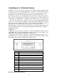

Attachment A: External Alarm
In addition to the motion detection executed by the internal software application, the
product can connect to external infrared detectors, beepers, and smoke detectors. For
more information about these external devices, contact to your local retailer, dealer or
installation service provider. This product provides a standard Alarm I/O for you.
This camera provides 4 sets of digital inputs (DIs) and 2 sets of digital outputs (DOs).
Pins 3 and 4 are designed for connection to external Sensor 1; Pins 3 and 5 for
external Sensor 2; Pins 3 and 6 for external Sensor 3; Pins 3 and 7 for external Sensor
4. All 5 pins are designed for connection to the C connection equipment and should
not access to voltage or current. Otherwise, the product will be damaged. Pins 8, 9, 10
and11 are relays to normally open (NO) or close (NC) these external devices. These 4
pins only act as relay output contacts and no power is output (dry contacts).
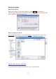
The default status for these 4 DI sets is NO. The gray color indicates the current status.
NC status can be selected by selecting Setting/ Application Setting/ Event/ Trigger/
Alarm Input Setting.
Applications:
1. When the status is NO, the connected C connection equipment should be NO as
well. When the C connection equipment is triggered, the status will change to NC.
The machine will detect this change and inform the system.
2. When the status is NC, the connected C connection equipment should be NC as
well. When the C connection equipment is triggered, the status will change to NO.
The machine will detect this change and inform the system.
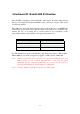
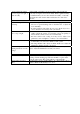
Pin Function
1 Audio In
2 Audio GND
3 Alarm Input #1/2/3/4 (K)
4 Alarm Input #1 (A)
5 Alarm Input #2 (A)
6 Alarm Input #3 (A)
7 Alarm Input #4 (A)
8 Alarm Output #1 (COM) Dry Contact
9 Alarm Output #1 (NO) Dry Contact
10 Alarm Output #2 (COM) Dry Contact
11 Alarm Output #2 (NC) Dry Contact
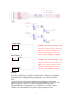
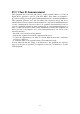
External Alarm I/O Circuit Diagram
82