PUMP OPERATIONS & MAINTENANCE MANUAL A050 - 1/2 INCH AIR OPERATED DOUBLE DIAPHRAGM PUMP all-flo.
TABLE OF CONTENTS SECTION 1 WARNINGS AND SAFETY PRECAUTIONS SECTION 2 MODEL DESIGNATION MATRIX SECTION 3 PRINCIPLES OF OPERATION SECTION 4 DIMENSIONAL DRAWINGS SECTION 5 PERFORMANCE CURVES 3 4-5 6 7-8 RUBBER DIAPHRAGMS...............................................................9 TPE DIAPHRAGMS.........................................................................9 PTFE DIAPHRAGMS......................................................................
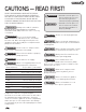
1 SECTION CAUTIONS — READ FIRST! READ THESE WARNINGS AND SAFETY PRECAUTIONS PRIOR TO INSTALLATION OR OPERATION. FAILURE TO COMPLY WITH THESE INSTRUCTIONS COULD RESULT IN PERSONAL INJURY AND OR PROPERTY DAMAGE. RETAIN THESE INSTRUCTIONS FOR FUTURE REFERENCE. WARNING = Hazards or unsafe practices which could result in severe personal injury, death or substantial property damage CAUTION = Hazards or unsafe practices which could result in minor personal injury, product or property damage.
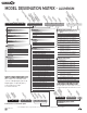
2 SECTION MODEL DESIGNATION MATRIX - ALUMINUM 1 1 FLUID CONNECTION TYPE 2 A = Aluminum P = Polypropylene (Glass Filled) 6 7 4 DIAPHRAGMS G = Geolast® S = Santoprene® T = PTFE with Santoprene® Backup N = Buna – N E = EPDM V = Viton® WET END REPAIR KIT Wet end kits are available and consist of diaphragms, (back-up diaphragms if required), balls, seats and seat o-rings. See matrix below.
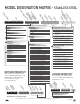
MODEL DESIGNATION MATRIX - STAINLESS STEEL 1 1 FLUID CONNECTION TYPE 2 P = Polypropylene (Glass Filled) A = Aluminum 6 7 4 DIAPHRAGMS S = Santoprene® T = PTFE with Santoprene® Backup N = Buna – N E = EPDM V = Viton® G = Geolast® WET END REPAIR KIT Wet end kits are available and consist of diaphragms, (back-up diaphragms if required), balls, seats and seat o-rings. See matrix below.
SECTION 3 PRINCIPLES OF OPERATION HOW AN AIR OPERATED DOUBLE DIAPHRAGM PUMP WORKS The air-valve directs pressurized air behind the diaphragm on the right, causing the diaphragm on the right to move outward (to the right). Since both the right diaphragm and the left diaphragm are connected via a diaphragm rod, when the right diaphragm moves to the right, the left diaphragm (through the action of the diaphragm rod) moves to the right also.
4 SECTION 1/2” PUMP DIMENSIONS ALUMINUM CENTER SECTION 1” MNPT OR 1” MBSP (x4) 1/2” FNPT or FBSP 11.2” (284mm) 9.5” (241mm) 6.7” (170mm) 1.8” (46mm) 10.3” (262mm) 6.4” (163mm) 0.3” (8mm) 3.2” (81mm) 3.6” (91mm) 4.0” (102mm) 1.1” (28mm) 2.3” (58mm) 4.4” (112mm) 5.4” (137mm) Note - Suction Right / Discharge Right are default ports. See part number matrix option code for additional porting options. all-flo.
SECTION 4 1/2” PUMP DIMENSIONS POLYPROPYLENE CENTER SECTION 1” MNPT OR 1” MBSP (x4) 1/2” FNPT or FBSP 11.2” (284mm) 9.5” (241mm) 6.3” (160mm) 6.3” (160mm) 1.8” (46mm) 10.3” (261.62mm) 0.3” (8mm) 7.3” (185mm) 4.1” (104mm) 3.6”(91mm) 4.0” (102mm) 1.8” (46mm) 3.2” (81mm) 4.4” (112mm) 5.4” (137mm) Note - Suction Right / Discharge Right are default ports. See part number matrix option code for additional porting options. 8 all-flo.
5 SECTION PERFORMANCE CURVES PERFORMANCE CURVE (1/2” RUBBER)* Performance Specifications 7.5 100 (6,8) 5 15.1 22.7 30.3 37.9 45.4 53 60.6 AIR CONSUMPTION (SCFM) 10 15 20 276 (83,9) 230 (69,9) 80 (5,4) 184 (55,9) 60 (4,1) 138 (41,9) 40 (2,7) 92 (27,9) 20 (1,3) 46 (13,9) 0 2 4 6 8 10 12 14 TOTAL HEAD IN FEET (METERS) PRESSURE INLET/OUTLET PSIG (BARS) DISCHARGE FLOW-Liters/Min. 120 (8,2) 16 DISCHARGE FLOW-U.S. Gals./Min.
SECTION 6 INSTALLATION, TROUBLESHOOTING AND MAINTENANCE INSTALLATION PIPING Whenever possible ensure the pump is installed using the shortest possible pipe lengths with the minimum amount of pipe fittings. Ensure all piping is supported independent of the pump. Suction and discharge piping should not be smaller than the connection size of the pump. When pumping liquids of high viscosity, larger piping may be used, in order to reduce frictional pipe loss.
SUGGESTED INSTALLATION Pressure Gauge with Optional Diaphragm Seal Pulsation Damper Isolation Valve Air Supply Filter Regulator Flex Connector Pressure Gauge with Optional Diaphragm Seal Inlet Optional Strainer Flex Connector This illustration is a generic representation of an air operated double-diaphragm pump. all-flo.
TROUBLESHOOTING PROBLEM EFFECT/SOLUTION Pump Will Not Cycle Discharge line closed or plugged Discharge filter blocked Check valve stuck Air filter blocked Air supply valve closed Air supply hooked up to muffler side of pump Compressor not producing air or turned off Muffler iced or blinded Diaphragm ruptured Plant air supply line ruptured Air valve wear/debris Pilot sleeve wear/debris Diaphragm rod broken Diaphragm plate loose Pumped Fluid Coming Out of Muffler Diaphragm ruptured Diaphragm plate loose In
OPERATION The Air-Operated Double Diaphragm Pump requires a minimum of 20 psig of air to operate, with some variation according to diaphragm material. Increasing the air pressure results in a more rapid cycling of the pump and thus a higher liquid flow rate. In order to not exceed 120 psig of inlet air pressure, and for accurate control of the pump, it is suggested to use a pressure regulator on the air inlet.
SECTION 7 REPAIR AND ASSEMBLY PUMP WET END REMOVAL REQUIRED TOOLS 1) One Wrench, 7/16 Inch 2) Two Wrenches, ½ Inch 3) Two Wrenches, ¾ Inch WARNING Prior to servicing the pump, ensure that the air and fluid lines are closed and disconnected. While wearing personal protective equipment, flush, drain and process liquid from the pump in a safe manner.
STEP 6 Remove the “O-Ring”, “Valve Seat” and “Ball” from the “Suction Manifold”. STEP 7 STEP 8 STEP 9 In order to remove both “Outer Chambers”, using two ½ inch wrenches, remove eight “Hex Head Cap Screws (5/16”–18 x 1-3/8”)” and eight “Hex Flange Nuts (5/16”-18)”. Remove both “Outer Chambers” from the “Intermediate”. Using two ¾ Inch wrenches, remove “Outer Diaphragm Plate”, “Diaphragm”, “Inner Diaphragm Plate” and “Flat Washer (1/4”)” from one side of the pump.
REPAIR AND ASSEMBLY AIR VALVE REMOVAL REQUIRED TOOLS WARNING Prior to servicing the pump, ensure that the air 1)One Wrench, 7/16 Inch 2) One Pick, General Purpose 3) One Pair of Pliers and fluid lines are closed and disconnected. While wearing personal protective equipment, flush, drain and process liquid from the pump in a safe manner. STEP 1 STEP 2 STEP 3 Using the 7/16 inch wrench, remove four “Hex Head Cap Screws (1/4”–20 x 3”)” and four flat washers (1/4”)”.
STEP 7 STEP 8 STEP 9 Remove the “Air Valve Spool” from the main “Air-Valve Assembly”. Using the pick, remove the “Lip Seal (Air Valve)” from the main “Air-Valve Assembly”. Using the pick, remove the second “Lip Seal (Air Valve)” from the main “Air-Valve Assembly”. To assemble the air valve, reverse the order of disassembly. During assembly, ensure that the open side of the lip-seals are both facing each other inward.
REPAIR AND ASSEMBLY PILOT VALVE REMOVAL REQUIRED TOOLS WARNING Prior to servicing the pump, ensure that the air 1) One Screwdriver, Phillips 2) Two Wrenches, 7/16 Inch and fluid lines are closed and disconnected. While wearing personal protective equipment, flush, drain and process liquid from the pump in a safe manner. STEP 1 STEP 2 STEP 3 Using the screwdriver, remove three “Phillips Flat-Head Mach Screws (#6-32 x 7/16)” in order to remove the “Retaining Plate”. Repeat for both sides of the pump.
To assemble the pilot valve, reverse the order of disassembly. Should process fluid have contact with the pilot valve o-rings, they should be replaced as swelling may occur and cause irregular operation. During assembly, ensure that the open side of the lip-seals are facing outward. Lubrication of the pilot sleeve assembly, with a non-synthetic lubricant, is recommended in order to facilitate re-assembly into the intermediate.
SECTION 8 EXPLODED VIEW & PARTS LIST ALUMINUM AND STAINLESS STEEL PUMPS WITH ALUMINUM CENTER SECTION 32 29 30 18 14 11 22 36 38 10 31 33 20 24 7 24 24 24 26 6 1 2 3 25 39 26 30 15 16 17 8 27 23 30 21 32 29 all-flo.
PARTS LIST ITEM DESCRIPTION QTY PUMP MODEL PART NO.
ITEM DESCRIPTION 23 O-Ring (Air Valve End Plug) QTY 1 PUMP MODEL ALL MODELS PART NO.
EXPLODED VIEW & PARTS LIST ALUMINUM AND STAINLESS STEEL PUMPS WITH PLASTIC CENTER SECTION 34 30 31 18 14 11 42 22 37 40 43 10 29 32 38 39 20 24 24 24 44 24 41 31 26 33 36 6 25 9 3 4 28 7 35 1 2 2 2 3 25 26 5 31 27 17 8 15 16 27 31 23 30 34 21 all-flo.
PARTS LIST ITEM DESCRIPTION QTY PUMP MODEL PART NO.
ITEM DESCRIPTION 23 O-Ring (Air Valve End Plug) QTY 1 PUMP MODEL ALL MODELS PART NO.
SECTION 9 ELASTOMERS & REPAIR KITS BUNA-N (NITRILE) GEOLAST® EPDM SANTOPRENE® VITON® FKM is a general purpose elastomer used with water and many oils. Temperature range 10°F to 180°F (-12C to 82C). is a general purpose elastomer with good resistance to many acids and bases. Temperature range -40°F to 280°F (-40C to 138C). is an elastomer with good corrosion resistance to a wide variety of chemicals. Temperature range -40°F to 350°F (-40C to 177C).
SECTION WARRANTY AND REGISTRATION 10 WARRANTY. All All-Flo products shall be covered by the standard All-Flo Limited Warranty in effect at the time of shipment. This warranty (which may be modified by All-Flo at any time) provides: MATERIALS SOLD ARE WARRANTED TO THE ORIGINAL USER AGAINST DEFECTS IN WORKMANSHIP OR MATERIALS UNDER NORMAL USE (RENTAL USE EXCLUDED) FOR FIVE YEARS AFTER PURCHASE DATE.
ALL-FLO is committed to the pursuit of designing and manufacturing the highest quality product available to industry. Since the beginning in 1986, All-Flo engineers have used their extensive knowledge of today’s engineered materials, advanced air system logic and manufacturing techniques to develop the superior group of lube-free, air-operated diaphragm pumps found in this catalog. Every pump is performance engineered and quality built to provide trouble-free service under the toughest conditions.