
User`s guide


Updating the Firmware
www.ti.com
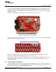
When opening the box, locate the debug connector header next to the target connector. Connect this
header to another CC Debugger (see Figure 18) or to a SmartRF05EB (see Figure 19). When using
SmartRF05EB, connect a 10-pin flat cable from the “Ext SoC Debug” plug (P3) on the EB to the “USB
Debug” plug (P2) on the CC Debugger. The dead debugger needs power, so connect the USB cable. Turn
on the SmartRF05EB or debugger - it should detect the USB Controller (CC2511) on the debugger.
Figure 18. Programming the Bootloader on the CC Debugger Using Another CC Debugger
Figure 19. Programming the Bootloader on the CC Debugger Using SmartRF05EB
18
CC Debugger SWRU197H–September 2010–Revised April 2014
Submit Documentation Feedback
Copyright © 2010–2014, Texas Instruments Incorporated