
User`s manual


11 - 12 11 - 12
MELSEC
11 TROUBLESHOOTING
11.5 Flowchart to Use when an Error Occurs During Data Linking
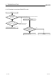
The following flowchart indicates when an error occurs during data linking is shown.
Contents of generated error
A value different from the schedule
enters the special link device
Section 11.5.1
Flowchart to use when a value different
from the schedule enters the special link
device
Reading from and writing to the
device cannot be done using the
communication function
Section 11.5.2
Flowchart to use when reading from
and writing to the device cannot be
done using the communication function
Communication stops during the user
program execution
Section 11.5.3
Flowchart to use when communication
is disabled from time to time during
user program execution
System goes down or resets during the
user program execution
Section 11.5.4
Flowchart to use when the system goes
down or resets during the user program
execution
11.5.1 Flowchart to use when unexpected value is input to specific link device
Check the following items.
1) Check for a station with link error using the network monitor in the monitoring
function.
2) Check the link parameter assignment range at the master station.
3) Check the device range used in the PLC program at the PLC.
4) Check, in the user program, argument data for the communication function
accessing the specific link device.