050WATT PORTABLE GENERATOR 866.393,3968 866.393.
1050W4 StrokeGenerator Tableof Contents 2 2 2 3 1. DESCRIPTION 2. UNPACKING 3. GENERAL SAFETY 4. OPERATION 3 PRE-OPERATION GROUNDING 4 DC APPLICATION 4 STARTING 4 ENGINE GENERATOR LOAD 5 BREAK-IN SHUT 5 OFF 5 AND PROTECTOR OIL WARNING 5 SYSTEM 6 5, MAINTENANCE INFREQUENT 6 USAGE 6 STORAGEMAINTENANCE 7 SCHEDULE 6, TROUBLESHOOTING 8 7. WIRING 9 DIAGRAM 8. EXPLODED 10 VIEW 11 9. PARTS LIST.
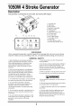
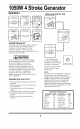
1050W4 StrokeGenerator Description This generator 9 is powered 2 1 by an air-cooled, four-stroke, OHV engine. 3 1. Fuel tank cap 2. Safty label 3.Control panel 4.Generator nameplate 5. Starting handle 6. Fuel petcock 7. Carburetor choke lever 8. DC circuit fuse 9. AC circuit fuse 121314 10. AC output socket 11. DC output socket 12. Pilot lamp 13. Engine ignition switch 14.
1050W4 StrokeGenerator Description OIL FILLER CAP (OIL GAUGE) 13. Never operate the generator with damaged, broken or missing parts. DO NOT operate the generator while any of the protective shrouds or guards are removed. 14. Do not refill the fuel tank while the engine is running. Use precautions to prevent fuel spillage during refills. Be sure the fuel tank cap is securely in place before starting the engine. Allow engine to coot for at least two minutes before refueling. UPPERLEVEL 15.
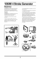
4 StrokeGenerator Grounding 1. Use the ground terminal on the generator to connect the unit to a suitable ground source. Securely fasten the end terminal of the ground wire terminal on the generator. STARTING 1. Remove all electrical loads from the generator. 2. Set the fuel switch to the open (ON) position. 3. Turn the engine switch in "ON" position. 4. Move the choke/run lever to the choke position. 2.
1050W4 StrokeGenerator Operation LOAD AND PROTECTOR Engine switch to Off position to RUN position ENGINE BREAK-IN The break-in period for the generator's engine is the first 25 hours of operation. During this timeframe, DO NOT exceed 75% of the generator's load limit. In other words, the maximum load during this break-in period should be no more than 700 watts. I_, CAUTION I 1. Total combined load through any combination of ALWAYS check the oil level before starting.
1050W4 StrokeGenerator Maintenance INFREQUENT USAGE If the generator is used infrequently, starting difficulties may occur. To help prevent this from happening, the generator should be started and run for approximately 30 minutes each week. 4. Pour approximately spark plug hole. one teaspoon of oil into 5. Pull starter cord several times to spread the oil throughout the cylinder. 6. Slowly pull the starter cord until resistance is left.
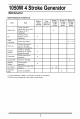
1050W4 StrokeGenerator Maintenance MAINTENANCESCHEDULE Part Item Check Spark plug Before First every starting month or 20 hours Every 3 months or 50 hours Every 6 months or 100 hours Every 12 Months or 300 hours condition, adjust gap and clean. Replace or fill if necessary Check oil level. Oil Replace or fill if necessary. Valve Clearance Check Check and adjust fuel hose for Fuel Line crack Exhaust Replace if necessary. Check for leakage.
1050W4 StrokeGenerator TroubleShooting Problem Possible Cause 1. Engine speed Corrective 1. Adjust is too slow engine Action speed(ask repair shop for help) 2. Open or shorted Zero output receptacles from wiring 2. Clean 3. Faulty capacitor 3. Replace 4. Open! shorted rotor or stator 4.Test windings 5. Open and reconnect capacitor wiring winding rectifier 1. Engine resistance, 1. Adjust is too slow replace if necessary 5.
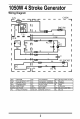
50W4 StrokeGenerator WiringDiagram C-BOX E/G I I ENG.SW. I I I I I I Y ! ! _"rll Y I Y II ;:::13 " "BL Y II D _ BL ..Lc BL moc I SOCKET -aL +_'] _._ DC m I E!G OSU SP G/R DI/D2 AC FU FC ENGINE OIL SENDING UNIT SPARK PLUG GENERATOR RECTIFIER AC FUSE FIELD WINDING ! MC SC DC PL REC DC FU ENG.
1050W4 StrokeGenerator Parts List 10
1050W4 StrokeGenerator PartsList No Description Part # Part No Bolt GB5780 M5"10 2 32 Out-fuel pipe 2 Spring Washer GB93 5 7 33 Fuet petcock GR1000C.05-03 1 3 Washer GB95 5 6 34 Spring washer GB/T93 1 4 Cover 1 35 Nut GB/T6184 5 Bolt 4 36 in-fuel pipe 6 Rear Cover, motor 1 37 Muffler exhaust cover GR1000C.02-01 7 Stator 1 38 Base plate GR1000C.02.