Automated Weather Observing System Installation and Checkout Manual × FAA APPROVED ECP180 — 2011 May 5 NOT FAA APPROVED 3000-017 Rev. C All Weather Inc. • 1165 National Drive • Sacramento, CA 95834 • USA • 800.824.5873 • www.allweatherinc.
Copyright © 201 , All Weather, Inc. All Rights Reserved. The information contained herein is proprietary and is provided solely for the purpose of allowing customers to operate and/or service All Weather, Inc. manufactured equipment and is not to be released, reproduced, or used for any other purpose without written permission of All Weather, Inc. Throughout this manual, trademarked names might be used.
AWOS 3000 INSTALLATION AND CHECKOUT C O N T E N T S Table of Contents 1. USING THIS MANUAL ......................................................... 1 1.1 General Precautions ....................................................... 1 7. MODEL 2040 ULTRASONIC WIND SENSOR .................. 58 7.1 Installation Guidelines .................................................. 58 7.2 Mounting ....................................................................... 58 7.3 Wiring ....................................
AWOS 3000 INSTALLATION AND CHECKOUT C O N T E N T S 14. MODEL 6500 THUNDERSTORM/LIGHTNING SENSOR 91 14.1 Overview ....................................................................... 91 14.2 RFI/EMI Precautions ..................................................... 91 14.3 Sensor Installation......................................................... 92 14.4 Checkout ....................................................................... 95 15. MODEL 6495 FREEZING RAIN SENSOR .......................
U S I N G T H I S M A N U A L 1 Chapter Using This Manual This manual details installation and checkout procedures for the All Weather, Inc. Automated Weather Observing System (AWOS) 3000. The AWOS 3000 is available in multiple configurations, with each AWOS configuration having a unique suite of sensors. This manual is organized around the individual sensors, with each sensor covered in its own chapter. A table at the beginning of each chapter lists the AWOS configurations that include the sensor.
C E N T R A L D A T A P R O C E S S O R 2 Chapter Central Data Processor CDP AWOS A AWOS AV AWOS I AWOS II AWOS III AWOS IIIP AWOS IIIT AWOS IIIPT AWOS IIIPTZ The Central Data Processor (CDP) is mounted in an industrial-grade rack (Figure 1) along with an Uninterruptible Power Source (UPS), VHF ground-to-air radio, voice/RMM (Remote Maintenance Monitoring)) modem, and any of the CDP options.
C E N T R A L 2.1 D A T A AWOS 3000 INSTALLATION AND CHECKOUT P R O C E S S O R CDP Installation The CDP is self-contained. It is installed indoors, at a location with access to AC power and any auxiliary communication and data lines required. Installation of the CDP primarily involves routing external cables into the CDP rack and connecting them to the CDP back panel. The installation of individual CDP options (AWOS Net, UHF Radio, etc.
C E N T R A L D A T A AWOS 3000 INSTALLATION AND CHECKOUT P R O C E S S O R 2. Using a hacksaw, trim the radial length of the antenna (Part M489103) to the length specified. Cover the end of the radiator with the plastic end cap provided with the antenna. 3. Coat the threaded ends of the radials with PTFE lubricant (supplied with antenna). Attach the radials to the radiator section. 4. Coat the threaded portion of the U-bolt with PTFE. Attach the U-bolt to the antenna as shown. 5.
C E N T R A L 2.1.4 D A T A AWOS 3000 INSTALLATION AND CHECKOUT P R O C E S S O R Connecting Optional Printer A parallel port is available on the CDP back panel for connection to a printer. Connect the printer as follows: 1. Connect the Centronics 36 end of the parallel printer cable (Part 20912-A) to the printer cable connector on the printer. 2. Feed the printer cable through the access hole in the top of the CDP enclosure. 3.
C E N T R A L D A T A AWOS 3000 INSTALLATION AND CHECKOUT P R O C E S S O R Figure 5. CDP Top-Shelf Components 2.3.1 Communications The communication options—RS-485 converter or UHF radio—mount to the CDP top shelf in front of the CPU Board/Hard Drive assembly. 2.3.1.1 RS-485 Landline Converter Installation When an RS-485 landline is used for communicating with the DCP, an RS-485 converter is installed on the top shelf using Velcro.
C E N T R A L D A T A AWOS 3000 INSTALLATION AND CHECKOUT P R O C E S S O R The following steps describe how to install the RS-485 converter kit. Figure 6 illustrates the connections. 1. Power off the CDP. 2. Affix one side of the Velcro backing to the underside of the converter. Attach the other side of the Velcro backing to the top shelf so that the converter is located at the front-left of the shelf with sufficient clearance from other components (see Figure 5). 3.
C E N T R A L D A T A AWOS 3000 INSTALLATION AND CHECKOUT P R O C E S S O R Figure 6.
C E N T R A L 2.3.1.2 D A T A AWOS 3000 INSTALLATION AND CHECKOUT P R O C E S S O R UHF Radio Installation When a radio data link is used between the DCP and the CDP, a UHF radio is mounted to the top shelf. The UHF antenna connects to the BNC connector labeled UHF on the back panel, The radio mounts to the shelf using Velcro.
C E N T R A L D A T A AWOS 3000 INSTALLATION AND CHECKOUT P R O C E S S O R Figure 7.
C E N T R A L D A T A AWOS 3000 INSTALLATION AND CHECKOUT P R O C E S S O R Connecting the UHF Antenna When a UHF radio data link is used for communication between the DCP and CDP, the antenna and antenna cable must be installed. A mast for the antenna should have been installed as part of the site preparation. The cable from the UHF antenna must be routed to the CDP rack and connected to the back panel. 1.
C E N T R A L 2.4 D A T A AWOS 3000 INSTALLATION AND CHECKOUT P R O C E S S O R CDP Bottom-Shelf Components The CDP rack’s bottom shelf (Figure 8) is fixed in place. Components are accessible through the rack’s front or side doors. The bottom shelf holds the optional AWOS Net. Figure 8. CDP Bottom-Shelf Components The UPS is housed in the base of the rack, beneath the bottom shelf. The CD drive rests on the UPS. When not in use, the keyboard is stowed on top of the UPS as well.
C E N T R A L 2.4.1.1 D A T A AWOS 3000 INSTALLATION AND CHECKOUT P R O C E S S O R AWOS Net CDP Installation The AWOS Net kit includes: • • • • • • • • Model 2211 AWOS Net Controller M491834-00 serial Y cable M492616-00 network cable M492634-00 network cable DB9 to Ethernet adapter, transmit DB9 to Ethernet adapter, receive M491849-00 power cable Velcro The following steps describe how to install the AWOS Net Controller on the bottom shelf of the CDP rack. Figure 9 illustrates the connections. 1.
C E N T R A L D A T A AWOS 3000 INSTALLATION AND CHECKOUT P R O C E S S O R Figure 9. AWOS Net Installation 2.4.1.2 Connecting the Local Network to the AWOS Net An Ethernet cable from the LAN must be routed to the CDP and connected to the back panel as follows: 1. Route the network cable to the CDP location. 2. Feed the cable through the access hole in the top of the CDP enclosure. 3. Connect the cable to the RJ-45 connector labeled AWOS Net on the front side of the back panel.
C E N T R A L 2.5 D A T A AWOS 3000 INSTALLATION AND CHECKOUT P R O C E S S O R GPS NTP Time Standard A Network Time Protocol server using a GPS receiver (see Figure 10) maintains time synchronization at the CDP. The server, housed in a small, oval package, is installed outside the CDP. It can often be affixed to the top of the rack, depending on satellite reception. Figure 10. GPS NTP Time Standard Server To install the GPS NTP Server: 1.
C E N T R A L 2.7 D A T A AWOS 3000 INSTALLATION AND CHECKOUT P R O C E S S O R Remote Displays Using AWOS Net An AWOS Net Controller may be used to receive AWOS data directly from the DCP and output it to a display or local network. When used to provide data over a local network, the controller is normally installed in the CDP rack as explained in Section 2.4.1. When used with remote displays, the AWOS Net controller is installed at the site of the remote display.
C E N T R A L D A T A AWOS 3000 INSTALLATION AND CHECKOUT P R O C E S S O R Figure 11. AWOS Net 2210 Installation and CDP Connections 2.7.1.1 CDP Connections 1. If a serial cable from an RS-485 converter or UHF radio is connected to the DCP connector on the CDP’s back panel, disconnect it. 2. Connect the M491834-00 serial Y cable to the DCP connector on the CDP back panel. 3. One of the Y cable’s ends (labeled AWOS NET) has a DB9 to RJ-45 adapter preinstalled.
C E N T R A L 2.7.1.2 D A T A AWOS 3000 INSTALLATION AND CHECKOUT P R O C E S S O R AWOS Net Controller Installation 1. Connect the other end of the CAT 5/6 Ethernet cable from the CDP to the RJ-45 adapter on the AWOS Net Controller. Do not connect it to the Ethernet jack (RJ-45 connector with green and yellow LEDs beside it). 2. Plug the power cable connected to the AWOS Net’s terminal block into the mating connector on the power adapter. 3.
C E N T R A L D A T A AWOS 3000 INSTALLATION AND CHECKOUT P R O C E S S O R Figure 12. AWOS Net 2210-R Installation and CDP Connection 2.7.2.1 CDP Connections Connect the CAT 5/6 Ethernet cable with bare wires in parallel with the DCP-to-CDP RS-485 wires in the terminal box that is also used to connect the DCP to the CDP. The bare wires on the Ethernet cable from the RJ-45 jack must be matched with the specified colors inside the terminal box.
C E N T R A L 2.7.2.2 D A T A AWOS 3000 INSTALLATION AND CHECKOUT P R O C E S S O R AWOS Net Installation 1. Connect the serial and power cable (pre-installed on the Communication Interface) to the AWOS Net Controller as shown in Figure 13. 2. Connect the customer-supplied CAT 5/6 Ethernet cable from the RJ-45 connector coupler on the Communication Interface to the RJ-45 connector coupler on the Ethernet cable whose bare wires you just connected to the terminal box. 3.
C E N T R A L D A T A AWOS 3000 INSTALLATION AND CHECKOUT P R O C E S S O R These steps explain how to install the UHF Radio Communication Package. Figure 14 illustrates the connections. See also in Chapter 17, Drawings, for additional information about the antenna and mast assembly and installation. Figure 14. AWOS Net 2210-U Connections 1. Install the UHF radio antenna to the mast. The antenna should be pre-cut at the factory for the standard AWOS frequency range of 450 – 470 MHz. 2.
C E N T R A L 2.8 D A T A AWOS 3000 INSTALLATION AND CHECKOUT P R O C E S S O R KVM Extender for Remote Operation The KVM Extender Kit (M488342-00) is used to interface a remote operator terminal to the CDP using a CAT6 Ethernet cable between the local and remote KVM Extender units, with the Local Unit connected to the CDP. This is necessary when the CDP is installed in an equipment room and the actual operator of the AWOS is located elsewhere, such as in the control tower.
C E N T R A L D A T A AWOS 3000 INSTALLATION AND CHECKOUT P R O C E S S O R 6. One power cable — The M491908-00 power cable is used to power the Local Unit from the CDP. 7. One Y-cable power adapter — The Y-cable is used to make it possible for the Local Unit to get power from the CPU board if another device such as the AWOS Net or VPN is already connected to the power connector on the CPU board. 8. Two power supplies – One power supply will power the Remote Unit...
C E N T R A L D A T A AWOS 3000 INSTALLATION AND CHECKOUT P R O C E S S O R Figure 17.
C E N T R A L 2.8.1 D A T A AWOS 3000 INSTALLATION AND CHECKOUT P R O C E S S O R Local Unit Installation The Local Unit of the KVM extender is essentially installed between the computer in the CDP and the keyboard/mouse combination, microphone, and speakers. The following steps summarized in Figure 18 describe the process to connect the Local Unit to the CDP. Care should be taken to keep all cables routed cleanly and added to cable bundles as necessary for neatness. Figure 18.
C E N T R A L D A T A AWOS 3000 INSTALLATION AND CHECKOUT P R O C E S S O R 1. Remove the two side doors on the CDP and the front door. 2. Remove the four screws holding the front panel to the rack rail in the enclosure (see Figure 5). Slide the top shelf out for easier access. 3. Connect the yellow connector on the KVM cable (see Figure 18) to the CPU connector on the front of the Local Unit. 4. Remove all the caps from the ends of the 3.5 mm mini stereo audio connectors on the KVM cable. 5.
C E N T R A L D A T A AWOS 3000 INSTALLATION AND CHECKOUT P R O C E S S O R Figure 20. Local Unit Back Connections 11. Connect the audio extension cable provided in the KVM Extender Kit onto the green speaker connector on the KVM cable. 12. Remove the right angle audio connector in the J8 SPK OUT jack on the peripheral interface board (Figure 21). Connect this to the green speaker connector on the back of the Local Unit (Figure 20).
C E N T R A L D A T A AWOS 3000 INSTALLATION AND CHECKOUT P R O C E S S O R 15. Remove the keyboard USB keyboard connector from the back panel of the CDP (see Figure 2 and Figure 8 for the back panel location and the connector location on the panel). Connect this cable to the keyboard connector on the back of the Local Unit. 16. Connect the remaining end of the USB cable provided with the KVM extender into the keyboard back panel where the keyboard cable was previously removed. 17.
C E N T R A L 20. D A T A AWOS 3000 INSTALLATION AND CHECKOUT P R O C E S S O R If the CPU power connector is already being used, use the Y-cable provided with the KVM Extender Kit to provide a power connection to the device on the lower shelf that is already connected. a. The connector with the pins is connected to the CPU power connector. b. Connect the cable to the AWOS Net or VPN to one of the two remaining connectors on the Y-cable. c.
C E N T R A L 2.8.2 D A T A AWOS 3000 INSTALLATION AND CHECKOUT P R O C E S S O R Remote Unit Installation The Remote Unit of the KVM extender is installed in the desired operational location for the user. The Remote Unit requires a standard AC power connection (100 – 240 V AC) within 6 feet of the Remote Unit. The following steps summarized in Figure 24 describe the process to connect the Remote Unit to the CDP.
C E N T R A L D A T A AWOS 3000 INSTALLATION AND CHECKOUT P R O C E S S O R 1. Place the monitor, keyboard, mouse, and microphone in the desired locations. 2. Connect the straight-through CAT6 Ethernet cable from the Local Unit to the REMOTE I/O connector on the back of the Remote Unit (Figure 17). WARNING: This is not an Ethernet connection. Do not connect the KVM to an Ethernet network. 3. Connect the blue VGA video cable from the monitor to the monitor connector on the back of the Remote Unit.
C E N T R A L 2.8.3 D A T A AWOS 3000 INSTALLATION AND CHECKOUT P R O C E S S O R KVM Extender Checkout 1. Perform a visual inspection once the Local Unit and Remote Unit connections have been completed to make sure they match the connections shown in Figure 18, Figure 23 (if the Y-cable adapter was used), and Figure 24. 2. Power on the Remote Unit. The link light on the front of the Remote Unit should be on to indicate the link between the Local Unit and the Remote Unit is working. 3.
C E N T R A L 2.9 D A T A AWOS 3000 INSTALLATION AND CHECKOUT P R O C E S S O R AWOS/ATIS Interface FCC Title 47 (regulation 87.527c) only allows one VHF frequency for sites that have both ATIS and AWOS systems. If an ATIS system is used at an airport, the AWOS/ATIS Interface connects the VHF and telephone modem outputs of both systems to one VHF transmitter and one telephone modem (see Figure 26).
C E N T R A L 2.9.1 D A T A AWOS 3000 INSTALLATION AND CHECKOUT P R O C E S S O R ATIS Peripheral Interface Cable (M491838-00) The ATIS Peripheral Interface Cable is used to connect the AWOS/ATIS Interface assembly to the CDP Peripheral Interface PCB. Figure 27 illustrates the connections. Figure 27. AWOS/ATIS Interface Assembly Connections to CDP Peripheral Interface PCB 1. Turn the CDP power off. 2.
C E N T R A L 2.9.2 D A T A AWOS 3000 INSTALLATION AND CHECKOUT P R O C E S S O R AWOS/ATIS Remote Switch Assembly Mount the Model 2941 Remote Switch used with the Model 2940 AWOS/ATIS Interface at the location where the AWOS/ATIS Interface is controlled from. The switch assembly can be mounted to a vertical or horizontal surface with the provided machine screws. The Model 2941 Remote Switch can be located up to 1000 feet away from the AWOS/ATIS Interface.
C E N T R A L D A T A AWOS 3000 INSTALLATION AND CHECKOUT P R O C E S S O R Figure 28 shows the AWOS/ATIS Interface connections. Figure 28. AWOS/ATIS Interface Connections 1. If a Remote Switch is used, connect its Ethernet patch cord to the BLACK jack. 2. Connect the supplied blue patch cord between the ATIS Peripheral Interface cable (using the coupler) and the BLUE jack on the back of the AWOS/ATIS Interface.
C E N T R A L D A T A AWOS 3000 INSTALLATION AND CHECKOUT P R O C E S S O R 3. Connect the WHITE patch cords between the Interface assembly’s WHITE jack and the ATIS’s VHF PTT Keying output, VHF audio output, and Telco audio output. The polarity of these wires is not important. a. Connect the GREEN wire pair to the VHF Audio output. b. Connect the BLUE wire pair to the Telco Audio output. c. Connect the BROWN wire pair to the PTT Keying output. 4.
C E N T R A L 2.10 D A T A AWOS 3000 INSTALLATION AND CHECKOUT P R O C E S S O R CDP Checkout 1. Check display operation. 2. Check that either the RS-485 converter or UHF radio connections are in place so that the CDP can display data from DCP. If the corresponding connections are already supported and in place on the DCP and sensors are connected to the DCP, you may view the data on the display to verify the operation of the serial landline or UHF radio link to the DCP. 3. Check keyboard operation. 4.
C E N T R A L 2.11 D A T A AWOS 3000 INSTALLATION AND CHECKOUT P R O C E S S O R CDP Block Diagram Figure 29 shows a block diagram of the CDP components and their connections. Many of the connections shown in Figure 29 are via the CDP back panel, and are listed in Table 1. Table 1.
D A T A AWOS 3000 INSTALLATION AND CHECKOUT P R O C E S S O R Figure 29.
D A T A C O L L E C T I O N P L A T F O R M 3 Chapter Data Collection Platform AWOS A AWOS AV AWOS I AWOS II AWOS III AWOS IIIP AWOS IIIT AWOS IIIPT AWOS IIIPTZ DCP 3.1 DCP Mounting The Model 1190 DCP mounts to the sensor tower using Unistrut. The Barometric Pressure sensor (Model 7190) and optional UHF Radio mount inside the DCP enclosure. Drawing 1190-007 in Chapter 17, Drawings illustrates the installation procedures.
D A T A 3.3 C O L L E C T I O N AWOS 3000 INSTALLATION AND CHECKOUT P L A T F O R M Auxiliary Sensor Wiring An auxiliary voltage output sensor (such as a solar radiation sensor) can be connected to the DCP via pins 5 and 6 of TB3. 1. Connect the positive lead from the auxiliary sensor to pin 5 of TB3. 2. Connect the negative lead from the auxiliary sensor to pin 6 of TB3. 3.4 +5 V Power A +5 V output is available at pin 4 of TB3.
D A T A 3.6.2 C O L L E C T I O N AWOS 3000 INSTALLATION AND CHECKOUT P L A T F O R M RS-485 Wiring When RS-485 communication is used to communicate with the CDP, pins 7, 9, and 10 of TB4 are used to make the connection. Rs-485 may be used for CDPs located up to 4000' (1200 m) from the CDP. 1. Connect the positive lead of the RS-485 line from the CDP to pin 9 of TB4. 2. Connect the negative lead of the RS-485 line from the CDP to pin 10 of TB4. 3.
D A T A 3.10 C O L L E C T I O N AWOS 3000 INSTALLATION AND CHECKOUT P L A T F O R M DC, Battery Backup, and Solar Power Wiring TB1 on the DCP backplane provides input power connections for a +15 V DC supply, backup battery power, and solar power. 3.11 +15 V DC Power Input The DCP is powered by the AC Interface Board and a power supply, which provides a +15V DC output. This +15 V is input to the DCP at pins 5 (+) and 6 (-) of TB1. 1. Connect the positive lead from the power supply to pin 5 of TB1.
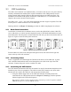
D A T A 3.14 C O L L E C T I O N AWOS 3000 INSTALLATION AND CHECKOUT P L A T F O R M DIP Switches Two DIP switch assemblies (SW1 and SW2) on the DCP backplane are used to set configuration parameters for the DCP. These switches are set at the factory and should not need to be changed. The first set of switches, SW1, specifies the communication method in use between the DCP and CDP (RS-232, RS-485, or UHF Radio). Table 2 shows the switch settings for each communication setup. Table 2.
D A T A 3.15 C O L L E C T I O N AWOS 3000 INSTALLATION AND CHECKOUT P L A T F O R M DCP Checkout 1. Verify that all cables are connected and in good condition. 2. Verify that the DIP switches are set to the factory settings specific to the sensor assembly and CDP communication link being supported. 3. Check that either the RS-485 connections to TB4 or UHF radio connections are in place so that the CDP can display data from DCP.
M O D E L 7 1 9 0 D U A L D I G I T A L B A R O M E T E R 4 Chapter Model 7190 Dual Digital Barometer Model 7190 Dual Digital Barometer 4.1 AWOS A AWOS AV AWOS I AWOS II AWOS III AWOS IIIP AWOS IIIT AWOS IIIPT AWOS IIIPTZ Installation The Model 7190 Dual Digital Barometer is located inside the DCP as shown in Figure 30, and is normally installed at the factory. Figure 30.
M O D E L 4.1.1 7 1 9 0 D U A L D I G I T A L AWOS 3000 INSTALLATION AND CHECKOUT B A R O M E T E R Pressure Connections The barometer is equipped with standard Clippard 11752-1 barbed pressure fittings with 10-32 external thread installed in the barometer. These fittings are ideal for 1/8" internal diameter tubing. If some other pressure fittings need to be used, it is possible to replace the standard barbed fittings.
M O D E L 7 1 9 0 D U A L D I G I T A L B A R O M E T E R AWOS 3000 INSTALLATION AND CHECKOUT Note the difference in readings for each Model 7190 sensor from the pressure standard reading using in Hg units. If the readings differ by more than 0.05 in Hg, replace the sensor. Otherwise, access the Airport > General tab on the CDP display by going through the Edit > Configuration menu. Then enter the two offsets and click OK to save them. Figure 31.
M O D E L 2 0 2 0 W I N D V A N E 5 Chapter Model 2020 Micro Response Wind Vane AWOS A Wind (2020/2030 or 2040) AWOS AV AWOS I AWOS II AWOS III AWOS IIIP AWOS IIIT AWOS IIIPT AWOS IIIPTZ Systems including a wind sensor consist of either a Model 2020 Micro Response Wind Vane and Model 2030 Anemometer in combination or a Model 2040 Ultrasonic Wind sensor. 5.
M O D E L 2 0 2 0 W I N D AWOS 3000 INSTALLATION AND CHECKOUT V A N E 3. Perform this step indoors where there is no air movement. Holding the sensor in a horizontal position, slide the vane shaft until it balances (the vane does not tip in either direction). Tighten one of the set screws and check that the vane tail is parallel to the shaft of the sensor. If not, use the nose weight to turn the shaft. Do not turn the shaft by holding the tail; the tail may break if twisted.
M O D E L 2 0 2 0 W I N D AWOS 3000 INSTALLATION AND CHECKOUT V A N E 9. When removing the wind vane for any reason in the future, do not loosen the mounting bolt on the sensor mount or remove the sensor mount from the crossarm. Remove the wind vane from the sensor mount by loosening the mounting bolt on the side of the sensor base. This will allow you to remove and reinstall the wind vane without repeating the orientation procedure. Section 6.1.
M O D E L 2 0 2 0 W I N D AWOS 3000 INSTALLATION AND CHECKOUT V A N E 2. With the sensor locked in position, stand at the direction benchmark and verify that the tail of the vane is aligned with the vane body. If the vane is not aligned, loosen the mounting screw located at the bottom of the Unistrut, align the sensor (and base) with the benchmark, and tighten the mounting bolt. 3. In turn, rotate the vane slowly through a full 360°, noting the reading on the LCD display.
M O D E L 2 0 2 0 W I N D AWOS 3000 INSTALLATION AND CHECKOUT V A N E 4. Verify that the vane’s movement is free and smooth. If it is not, replace the bearings. The shaft should turn freely at all times. 5. Inspect all mounting hardware and cable assemblies for wear and damage. Replace as necessary. 6. Apply a thick coating of silicon lubricant to the connector shell after the connector is attached and in place.
M O D E L 2 0 3 0 A N E M O M E T E R 6 Chapter Model 2030 Anemometer AWOS A Wind (2020/2030 or 2040) AWOS AV AWOS I AWOS II AWOS III AWOS IIIP AWOS IIIT AWOS IIIPT AWOS IIIPTZ Systems including a wind sensor consist of either a Model 2020 Micro Response Wind Vane and Model 2030 Anemometer in combination or a Model 2040 Ultrasonic Wind sensor. 6.1 Installation This instrument is thoroughly tested and fully calibrated at the factory and is ready for installation.
M O D E L 6.1.2 2 0 3 0 AWOS 3000 INSTALLATION AND CHECKOUT A N E M O M E T E R Mounting The Model 2030 Anemometer must be completely assembled (Section 6.1.1) before it is mounted on the tower. The Model 2020 Micro Response Wind Vane and Model 2030 Anemometer mount to the face of the tower using the M403256-01 mounting kit. The mounting kit includes a crossarm, mounting bolts, and all necessary hardware. The crossarm is assembled first, and is then mounted on the tower.
M O D E L 2 0 3 0 AWOS 3000 INSTALLATION AND CHECKOUT A N E M O M E T E R 2. Connect a Model 1231 run-up motor to the anemometer shaft and power the motor on. The DCP’s LCD display should read between 79 and 81 knots. 3. Replace the cup assembly. 4. Inspect the anemometer cups for damage, and replace if necessary. The following test should be performed in windless conditions.
M O D E L 2 0 4 0 U L T R A S O N I C W I N D S E N S O R 7 Chapter Model 2040 Ultrasonic Wind Sensor AWOS A Wind (2020/2030 or 2040) AWOS AV AWOS I AWOS II AWOS III AWOS IIIP AWOS IIIT AWOS IIIPT AWOS IIIPTZ Systems including a wind sensor consist of either a Model 2020 Micro Response Wind Vane and Model 2030 Anemometer in combination or a Model 2040 Ultrasonic Wind sensor. 7.1 Installation Guidelines 7.
M O D E L 2 0 4 0 U L T R A S O N I C W I N D S E N S O R AWOS 3000 INSTALLATION AND CHECKOUT above it that is half blue and half silver (see Figure 34). Align the blue/silver boundary with the red dot, which indicates the North side of the sensor. Mount the sensor to the crossarm while on the ground, before installing the crossarm on the tower. Figure 34. Model 2040 North Alignment Mark Refer to drawing M488270-01-007 in Chapter 17, Drawings during installation. 1.
M O D E L 7.3 2 0 4 0 U L T R A S O N I C W I N D S E N S O R AWOS 3000 INSTALLATION AND CHECKOUT Wiring This section describes the wiring for the three Model 2040 Ultrasonic Wind sensors. Drawing M488274-01-003 shows the heater DIN rail mounting and wiring connections, and the details of the wiring connections to the heater are shown in Figure 35 and in Drawing M488274-01-019 in Chapter 17, Drawings. 7.3.
M O D E L 2 0 4 0 U L T R A S O N I C W I N D S E N S O R AWOS 3000 INSTALLATION AND CHECKOUT Figure 35.
M O D E L 7.3.3 2 0 4 0 U L T R A S O N I C W I N D S E N S O R AWOS 3000 INSTALLATION AND CHECKOUT Model 2040HH Wiring The Model 2040HH signal wires connect to the RS-422/RS-232 converter installed inside the DCP. With this high-heat version of the sensor, a transformer is installed on a bracket over the Barometric Pressure sensor inside the DCP. A terminal block is installed on the DIN rail inside the DCP. The sensor cable uses seven twisted pairs of a cable such as the Belkin Ref.
M O D E L 5 1 9 0 T E M P E R A T U R E / R H S E N S O R 8 Chapter Model 5190 Temperature/RH Sensor AWOS A Model 5190 Temp/RH 8.1 AWOS AV AWOS I AWOS II AWOS III AWOS IIIP AWOS IIIT AWOS IIIPT AWOS IIIPTZ Installation 1. The MARS should not be installed on the tower and power should not be connected. This is important to prevent electrical shock and to avoid damage to internal wiring, as well as to the fan blades. 2. Connect the probe cable to the probe. 3.
M O D E L 5 1 9 0 T E M P E R A T U R E / R H S E N S O R AWOS 3000 INSTALLATION AND CHECKOUT 12. Route the cable down the tower in the most convenient manner. Lace or strap the cable approximately every 12 inches. Loose cables will rub against the tower in high winds, and the cable insulation could be destroyed. Use ultraviolet-resistant cable ties, tape, or metal strapping. Use caution to avoid damaging the outer jacket of the cable. 13.
M O D E L 5 1 9 0 T E M P E R A T U R E / R H S E N S O R AWOS 3000 INSTALLATION AND CHECKOUT • The reference sensor can take up to ten minutes to stabilize, as the sensor body may have absorbed or lost heat from contact with your body or from storage conditions. As you observe the readings, the two sensors may start out several degrees apart, but will slowly approach each other. Do not take any official reading until after the temperatures have settled.
M O D E L 8 1 9 0 M A R S 9 Chapter Model 8190 Motor Aspirated Radiation Shield AWOS A Model 8190 MARS AWOS AV AWOS I AWOS II AWOS III AWOS IIIP AWOS IIIT AWOS IIIPT AWOS IIIPTZ The Motor Aspirated Radiation Shield (MARS) is designed for tower installations. Mounting hardware, including mounting brackets and U-bolts, is provided. 9.
M O D E L 9.3 8 1 9 0 AWOS 3000 INSTALLATION AND CHECKOUT M A R S Checkout 1. Apply power to the MARS and check to see that the fan is rotating. Check to ensure that all mounting hardware is securely fastened. Verify sensor operation. 2. Remove the MARS fan fuse (F1) at the DCP and verify that the DCP indicates a fan failure. 3. Replace fuse F1. Verify the fan failure indication changes to OK within a couple of minutes. Figure 36.
M O D E L 6 0 2 1 T I P P I N G B U C K E T R A I N G A U G E 10 Chapter Model 6021 Tipping-Bucket Rain Gauge AWOS A Model 6021 Rain Gauge 10.1 AWOS I AWOS II AWOS III AWOS IIIP AWOS IIIT Option AWOS IIIPT AWOS IIIPTZ Option Option Siting 10.2 AWOS AV Site the gauge on a level base above the maximum seasonal snow depth. Locate the site in an area free from strong winds and large obstructions. Large open and level areas (i.e.
M O D E L 6 0 2 1 T I P P I N G B U C K E T R A I N G A U G E AWOS 3000 INSTALLATION AND CHECKOUT 3. Connect the other end of the cable to TB3 at the DCP as follows: a. BLACK and SHIELD wires to TB3, Pin 8 b. WHITE wire to TB3, Pin 7 4. Replace the collection funnel, making sure that its heater cable is plugged into the heater terminal box. 5. Secure the two side screws. 6. Connect the power cord to AC power. 10.2.
M O D E L 8 3 6 4 - E V I S I B I L I T Y S E N S O R 11 Chapter Model 8364-E Visibility Sensor AWOS A Model 8364-E Visibility Sensor AWOS AV AWOS I AWOS II AWOS III AWOS IIIP AWOS IIIT AWOS IIIPT AWOS IIIPTZ The Model 8364-E consists of the visibility sensor (two emitters and two detectors), a day/night sensor, and a visibility controller. 11.1 Sensor Siting The following are guidelines for installing the Model 8364-E Visibility sensor. Please consult FAA order 6560.
M O D E L 11.2 8 3 6 4 - E V I S I B I L I T Y AWOS 3000 INSTALLATION AND CHECKOUT S E N S O R Visibility Sensor Installation Follow the instructions below and refer to Drawings 8364-E-003 and 8364-E-007 in Chapter 17, Drawings to assemble and install the sensor: 1. Place the crossmember onto the mast so that the mast slides into the crossmember base. There are labels on either end of the crossmember; one reads “POLE” and the other reads “EQUATOR”.
M O D E L 11.3 8 3 6 4 - E V I S I B I L I T Y AWOS 3000 INSTALLATION AND CHECKOUT S E N S O R Visibility Control Board Installation The visibility control board mounts on the mast below the sensor using the M488173-01 mounting kit. 1. Mount the visibility control board on the mast with the top of the enclosure 5'6" (167 cm) from ground level, or at least 3 feet (1 meter) above maximum snow level. 2. Cables are identified with labels at their ends.
M O D E L 11.4 8 3 6 4 - E V I S I B I L I T Y AWOS 3000 INSTALLATION AND CHECKOUT S E N S O R Power Connection The following steps explain how to connect AC power to the 8364-E controller board. 1. Route power for the sensor through conduit or through a 3/8" strain relief installed in one of the two cutouts on the left side on the underside of the visibility controller board. 2. Terminate the AC power cable to TB1 on the controller board as shown in Figure 39. Figure 39.
M O D E L 8 3 6 4 - E V I S I B I L I T Y AWOS 3000 INSTALLATION AND CHECKOUT S E N S O R Figure 40. Ground Cable Installation 11.6 Signal Connections The Visibility sensor communicates with the DCP via an RS-485 serial connection. 1. Connect the data cable (T600503-00) to TB2 on the visibility control board as follows: BLACK wire (RS-485 (-)) to TB2, Pin 1 WHITE wire (RS-485 (+)) to TB2, Pin 2 RED wire (GND) to TB2, Pin 7 2.
M O D E L 11.7 8 3 6 4 - E V I S I B I L I T Y AWOS 3000 INSTALLATION AND CHECKOUT S E N S O R Additional Kits The following sections provide installation instructions for the additional kits available for the 8364-E. 11.7.1 Day/Night Sensor Kit (Part Number M403326-00) Installation The Day/Night sensor installs on the underside of the visibility controller enclosure and connects to J7 on the controller board (see Drawing M403326-00-003 in Chapter 17, Drawings).
M O D E L 8 3 6 4 - E V I S I B I L I T Y AWOS 3000 INSTALLATION AND CHECKOUT S E N S O R 5. The BATTERY START switch is located in the upper left of the control board just to the left of the large, rectangular component U4. To initiate battery power, depress the BATTERY START button and hold it down for 3–4 seconds. 6. The backup battery does not power the sensor head heaters, so performance will be somewhat degraded when running from battery power in cold temperatures. 7.
M O D E L 8 3 6 4 - E V I S I B I L I T Y AWOS 3000 INSTALLATION AND CHECKOUT S E N S O R 8. Remove the calibration paddle at this point and insert a piece of black foam over each emitter opening so that no emitted radiation will reach the detectors. Press the # key to continue. Note: If the emitters can't be completely covered, the calibration procedure will not be able to reliably get within the required 3% accuracy.
M O D E L 8 3 6 4 - E V I S I B I L I T Y AWOS 3000 INSTALLATION AND CHECKOUT S E N S O R 11.8.2 Battery Backup Checkout Check the Battery Backup operation. 1. Turn the main power switch off. The power switch is located on the AC Interface board, a smaller printed circuit board mounted in the lower right corner of the control board enclosure below the control board. 2. Verify that the “WATCHDOG” LED continues to blink approximately once per second. 3. Turn the main power switch back on. Figure 41.
M O D E L 8 3 3 9 C E I L O M E T E R 12 Chapter Model 8339 Ceilometer AWOS A AWOS AV AWOS I AWOS II Model 8339 Ceilometer 12.1 AWOS III AWOS IIIP AWOS IIIT AWOS IIIPT AWOS IIIPTZ Unpacking The 8339 Ceilometer is a precision optical/electronic instrument and should be handled with extreme care at all times. When the equipment is received, check that all parts listed on the packing slip are accounted for, and inspect the equipment for visible transport damage.
M O D E L 12.2 8 3 3 9 AWOS 3000 INSTALLATION AND CHECKOUT C E I L O M E T E R Installation The 8339 must be firmly mounted to a vertical 2½" mast for proper operation. Any movement of the 8339 arising from wind or other causes will reduce the accuracy of the ceilometer. The ceilometer should be installed in an open area away from trees, buildings, or other obstructions.
M O D E L 8 3 3 9 AWOS 3000 INSTALLATION AND CHECKOUT C E I L O M E T E R 12.2.1.3 Heater/Blower The Heater/Blower mounts on the mast using the supplied Unistrut and clamps. 1. Mount the Heater/Blower on the mast as shown in installation drawing 83396-00-007 in Chapter 17, Drawings. 2. Note that the Heater/Blower installs so that its mounting brackets fit between the Ceilometer’s mounting brackets (see Figure 43).
M O D E L 8 3 3 9 AWOS 3000 INSTALLATION AND CHECKOUT C E I L O M E T E R 12.2.3 Ceilometer Data Connection 1. Connect the data cable's circular connector to the CEILOMETER DATA connector on the underside of the ceilometer (see Figure 45). 2. Connect the other (unterminated) end of the cable to TB1 on the 11905-F daughter board at the DCP as follows: a. Connect the red wire to TB1, pin 1 b. Connect the white wire to TB1, pin 2. c. Connect the black and shield wires to TB1, pin 3. Figure 45.
M O D E L 8 3 3 9 AWOS 3000 INSTALLATION AND CHECKOUT C E I L O M E T E R Figure 46. Desiccant Installation 12.2.3.4 Final Steps 1. Ensure that the circuit breaker on the power supply is in the “ON” position. 2. Verify that DIP switch SW1 on the data acquisition board is configured for 8339 Native Format (SW1 switches 1 and 2 ON). Figure 47.
M O D E L 12.3 8 3 3 9 AWOS 3000 INSTALLATION AND CHECKOUT C E I L O M E T E R Checkout 1. Check blower operation by covering the receiver window with an opaque object (such as a sheet of paper) and verifying that the blower turns on. This may take up to 30 seconds. 2. Verify that that the Ceilometer is communicating properly with the DCP and that there are no status errors.
M O D E L 6 4 9 0 P R E S E N T W E A T H E R S E N S O R 13 Chapter Model 6490 Present Weather Sensor AWOS A AWOS AV AWOS I AWOS II AWOS III Model 6490 Present Weather Sensor 13.1 AWOS IIIP AWOS IIIT AWOS IIIPT AWOS IIIPTZ Siting and Installation Guidelines In general, the sensor should be located on level or slightly sloping ground where the sensor site will be exposed to the same environment as the area around it.
M O D E L 6 4 9 0 P R E S E N T W E A T H E R S E N S O R AWOS 3000 INSTALLATION AND CHECKOUT For AWOS installations, All Weather Inc. recommends that the sensor head be mounted on the sensor tower at a height of ten feet above the tower base. Install the junction box on the tower near the AWOS DCP junction box. • The installation must be rigid so that wind-induced vibration does not cause false alarms.
M O D E L 6 4 9 0 P R E S E N T W E A T H E R S E N S O R AWOS 3000 INSTALLATION AND CHECKOUT CAUTION Do NOT drill holes in any portion of the sensor head or electronics enclosure! Doing so will void the warranty and may allow water to enter the enclosure! 1. Install the waterproof cable glands or conduit fittings in two (2) holes in the bottom of the electronics enclosure for the AC and RS-485 cables. 2. The head should mount at about 10 feet up the tower (see Figure 49).
M O D E L 6 4 9 0 P R E S E N T W E A T H E R S E N S O R AWOS 3000 INSTALLATION AND CHECKOUT 3. Rotate the sensor head until the receive lens is facing north. 4. Tighten the U-bolt nuts when the orientation is correct. (Do not over tighten such that the mounting plate is bent). 5. Secure the head cables to the pole every 1-meter using tie-wraps or other straps. 6. Connect the 2 sensor head cables to the electronics enclosure connectors.
M O D E L 6 4 9 0 P R E S E N T W E A T H E R AWOS 3000 INSTALLATION AND CHECKOUT S E N S O R Table 4.
M O D E L 13.4 6 4 9 0 P R E S E N T W E A T H E R S E N S O R AWOS 3000 INSTALLATION AND CHECKOUT Checkout 1. With a clean finger, touch the lenses in front of the disc-shaped heaters which are bonded to the upper and lower inside surface of lenses. The lens surfaces should be slightly warmer to the touch than the ambient temperature. 2. Check the strength of the carrier signal by displaying the present weather status screen on the DCP display (press the * or # keys until the screen is displayed).
M O D E L 6 5 0 0 T H U N D E R S T O R M / L I G H T N I N G S E N S O R AWOS 3000 INSTALLATION AND CHECKOUT 14 Chapter Model 6500 Thunderstorm/Lightning Sensor AWOS A AWOS AV AWOS I AWOS II AWOS III Model 6500 Thunderstorm Detector 14.1 AWOS IIIP AWOS IIIT AWOS IIIPT AWOS IIIPTZ Overview The Thunderstorm/Lightning sensor package (consisting of an antenna mounted to a 28" x 32" ground plane and a processor housed in a NEMA 4X enclosure) mounts to a 2½" mast (2.875" O.D.
M O D E L 6 5 0 0 T H U N D E R S T O R M / L I G H T N I N G S E N S O R AWOS 3000 INSTALLATION AND CHECKOUT • Telephone antennas - 4 ft. (1.2 m) • VHF communication antennas - 1 ft. (0.3 m) • Any current-carrying cable - 2 ft. (0.6 m) In addition to the above restrictions, certain site installations may have to be scrutinized more carefully from an RFI/EMI perspective.
M O D E L 6 5 0 0 T H U N D E R S T O R M / L I G H T N I N G S E N S O R AWOS 3000 INSTALLATION AND CHECKOUT 5. Tighten the bolts. 6. Set the sensor package (antenna, ground plane, enclosure, and bracket) on the mast, and fasten loosely with two U-bolts, lock washers, and flat washers as shown in Figure 52. Figure 52. Sensor Package Mounting 7.
M O D E L 6 5 0 0 T H U N D E R S T O R M / L I G H T N I N G S E N S O R AWOS 3000 INSTALLATION AND CHECKOUT 10. The sensor enclosure lid is equipped with hinged bolts (see Figure 54) to allow the box to be opened with the ground plane attached. Grasp both sides of the ground plane and lift straight up as far as possible (about 3"), then tilt the ground plane and lid over carefully to gain access to the enclosure interior. When fully open, the ground plane will rest against the side of the enclosure.
M O D E L 6 5 0 0 T H U N D E R S T O R M / L I G H T N I N G AWOS 3000 INSTALLATION AND CHECKOUT S E N S O R Table 5. Thunderstorm/Lightning Sensor Signal and Power Wiring 14.4 Sensor Interface Board TB1 Pin Function Color DCP TB4 Pin 4 RS-485 (+) WHITE 1 5 RS-485 (–) BLACK 2 6 GROUND RED 7 AC Interface Board TB1 Pin Function Color 1 HOT BLACK 2 3 NEUTRAL GROUND WHITE GREEN Checkout 1.
M O D E L 6 4 9 5 F R E E Z I N G R A I N S E N S O R 15 Chapter Model 6495 Freezing Rain Sensor AWOS A AWOS AV AWOS I AWOS II AWOS III AWOS IIIP Model 6495 Freezing Rain Sensor 15.1 AWOS IIIT AWOS IIIPT AWOS IIIPTZ Mechanical Installation The Freezing Rain Sensor comes pre-installed on a flat mounting plate, which in turn attaches to a standard 2 ½" mast using U-bolts (see Figure 56). Mounting Bolts (Access from back of sensor) Mounting Plate Figure 56.
M O D E L 6 4 9 5 F R E E Z I N G R A I N S E N S O R AWOS 3000 INSTALLATION AND CHECKOUT 3. Install the second U-bolt through the bottom two mounting holes and fasten with flat washers, lock washers, and nuts. 4. Tighten all hardware. 15.2 Power Connections The power cable is pre-terminated internally. The cable external end of the power cable should be terminated in a junction box at the bottom of the freezing rain mounting pole. 15.
F O L D O V E R T O W E R O P T I O N S 16 Chapter Foldover Tower Operations 16.1 Lowering the Tower To lower the hinged section of the tower: 1. Remove and retain the four nuts from the bottom two U-bolt clamps. Remove the U-bolt clamps. 2. If a padlock is used to secure the leverage arm, remove the padlock. 3. Pull the bottom of the leverage arm outward from the tower. 4. Crank the winch cable counterclockwise to continue lowering the tower. Lower the tower slowly.
D R A W I N G S 17 Chapter Drawings The following pages contain supplemental installation drawings and wiring diagrams. They are arranged in the same order as the chapters of this manual, according to the sensor or component to which they pertain.
This antenna is supplied to operate satisfactorily within the frequency range(s) specified on the carton label. Some models require cutting of radiator and/or radials in accordance with Figure 11. If the antenna is to be used over a range of frequencies, the element lengths should be chosen for mid-range or favor the element length for the most used, or the frequency requiring the greatest range. ASSEMBLING THE ANTENNA 1) Select antenna location and route cable from set to antenna.
Lengths on chart are approximate. For finer tuning, use a VSWR bridge if antenna is to be used for transmitting. Remove vinyl cap before measuring and cutting. Slide vinyl cap back on after cutting. UHF/VHF Antenna Assembly (cont.) Except as may otherwise be specified by contract, this document and the data disclosed herein and herewith is not to be used, reproduced, or disclosed, in whole or in part, to anyone without the written permission of All Weather Inc.
Base and Roof Mount. Heavy-gauge steel swivel base fits the slope of most roofs. 1¼" mast locks into U-bolt. Radio Shack P/N 15-889 Vent Pipe Mount. Brackets attach to 2" to 5" vent pipes (GC model fits 2" to 4" vents). 1¼" mast clamps into place. Radio Shack P/N 15-893 GC Electronics P/N 8802 12" Wall Mounts. Secures 1¼" mast 12" from side of building. Radio Shack P/N 15-885 GC Electronics P/N 8312 4" Wall Mounts. Secures 1¼" mast 4" from side of building.
All Weather Inc. 1165 National Drive Sacramento, CA 95818 Fax: 916.928.1165 Phone: 916.928.1000 Toll Free: 800.824.