
Specifications


CENTRAL DATA PROCESSOR AWOS 3000 INSTALLATION AND CHECKOUT
9
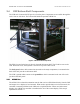
2.3.1.2 UHF Radio Installation
When a radio data link is used between the DCP and the CDP, a UHF radio is mounted to the top
shelf. The UHF antenna connects to the BNC connector labeled UHF on the back panel, The
radio mounts to the shelf using Velcro.
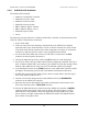
The radio kit includes:
• Model 20980-A UHF Radio
• M491860-00 serial cable
• M491847-00 power cable
• M491852-00 antenna cable
• Velcro
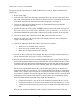
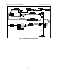
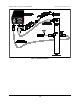
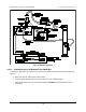
The following steps describe how to install the radio kit. Figure 7 illustrates the connections. See
also in Chapter 17, Drawings, for additional information about the antenna and mast assembly
and installation.
1. Power off the CDP.
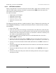
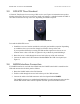
2. Affix one side of the Velcro backing to the underside of the UHF radio. Attach the other
side to the top shelf. Locate so that the radio is in the front-left of the shelf with sufficient
clearance from other components (see Figure 5). Position the connectors so that they face
the “inside” or the peripheral interface board.
3. Connect the female end of the DB9 connector on cable M491860-00 to the radio’s
DATA PORT 1 connector.
4. Connect the other end of the cable to the DCP connector on the back panel (see Figure 7).
This connection will be modified if the AWOS Net option is installed (see Section 2.4.1.1).
5. Connect one end of the included antenna cable (M491852-00) to the BNC connector on
the radio.
6. Connect the other end of the antenna cable to the connector on the back side of the back
panel labeled UHF.
7. Connect the M491847-00 power cable’s small connector to the POWER connector on
the radio.
8. Connect the other end of the power cable to the mating connector on the power supply’s
unused power cable.