
Specifications


DATA COLLECTION PLATFORM AWOS 3000 INSTALLATION AND CHECKOUT
43
3.6.2 RS-485 Wiring
When RS-485 communication is used to communicate with the CDP, pins 7, 9, and 10 of TB4
are used to make the connection. Rs-485 may be used for CDPs located up to 4000' (1200 m)
from the CDP.
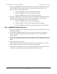
1. Connect the positive lead of the RS-485 line from the CDP to pin 9 of TB4.
2. Connect the negative lead of the RS-485 line from the CDP to pin 10 of TB4.
3. Connect the ground lead of the RS-485 line from the CDP to pin 7 of TB4.
3.6.3 UHF Radio
The UHF radio antenna is installed on the tower as part of the site preparation. The 25' antenna
cable (Model M491541) must be attached to the end of the antenna using the UHF connector.
Attach the BNC connector at the other end of the antenna cable to the UHF radio installed in the
DCP as shown on the M403316-003 drawing. Make sure that the UHF radio in the DCP is
grounded to the DCP backplane.
Secure the antenna cable to the tower approximately every 3 feet using cable ties.
See the UHF/VHF Antenna Assembly drawings in Chapter 17, Drawings for additional
information.
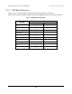
3.7 RS-485 Expansion Port
The RS-485 connections on TB4 (1–2, 7) are used to connect the 6490 Present Weather sensor,
and the 6500 Thunderstorm/Lightning sensor, and the remaining RS-485 connections on TB4
(3–4, 7) are used to connect the 8364-E Visibility sensor. Connections for these sensors are
covered in the chapter in this manual dedicated to the sensor.
3.8 Serial Sensor Wiring
When using a 2040 Ultrasonic Wind Sensor, 8339 Ceilometer, or 6495 Freezing Rain sensor, a
separate “serial sensor interface daughter board” is added to the backplane to interface each
sensor. There is room for up to three such daughter boards, one for each sensor, which are
connected to one another via an internal RS-485 bus. Connect the sensors’ signal cables to their
appropriate daughter boards at TB1 pins 1–3 on the daughter boards.
3.9 AC Power Wiring
AC line power is input to the DCP via the AC Interface Board (M404802). Connect incoming
AC power to TB1 on the AC Interface Board (not TB1 on the DCP backplane) as follows:
1. Connect the AC LINE (hot) wire to TB1, pin 1.
2. Connect the AC NEUTRAL wire to TB1, pin 2.
3. Connect the AC GROUND wire to TB1, pin 3.