
Specifications

MODEL 8364- E VISIBILITY SENSOR AWOS 3000 INSTALLATION AND CHECKOUT
74
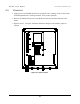
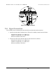
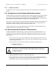
Figure 40. Ground Cable Installation
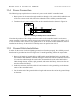
11.6 Signal Connections
The Visibility sensor communicates with the DCP via an RS-485 serial connection.
1. Connect the data cable (T600503-00) to TB2 on the visibility control board as follows:
BLACK wire (RS-485 (-)) to TB2, Pin 1
WHITE wire (RS-485 (+)) to TB2, Pin 2
RED wire (GND) to TB2, Pin 7
2. Connect the other end of the data cable to TB4 at the DCP as follows:
BLACK wire (RS-485 (-)) to TB4, Pin 4
WHITE wire (RS-485 (+)) to TB4, Pin 3
RED wire (GND) to TB4, Pin 7