
Specifications


MODEL 6500 THUNDERSTORM/LIGHTNING SENSOR AWOS 3000 INSTALLATION AND CHECKOUT
92
• Telephone antennas - 4 ft. (1.2 m)
• VHF communication antennas - 1 ft. (0.3 m)
• Any current-carrying cable - 2 ft. (0.6 m)
In addition to the above restrictions, certain site installations may have to be scrutinized more
carefully from an RFI/EMI perspective. Finding locations to mount the ground plane and antenna
that will minimize interference from RFI/EMI sources can be enhanced by the use of standard
RFI measuring equipment. The recommended equipment for monitoring the proposed
installation area is a typical spectrum analyzer with a broadband conical antenna. The spectrum
analyzer should be set up to scan the frequencies of concern (100-500 MHz) for the typical VHF
and UHF radio links near the installation.
Once it has been determined that there is significant interference, it is imperative that the
lightning sensor be moved to a location as far from the interfering device as possible. Under no
circumstances should the lightning sensor antenna and ground plane be placed within one foot
of either a VHF or UHF transmitting antenna.
Note that it might not be possible to completely comply with the minimum distance requirements
from significant RFI sources when installing the sensor in an oil rig or rooftop environment.
Consult All Weather Inc. for guidance if this appears to be an issue.
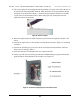
14.3 Sensor Installation
The Thunderstorm/Lightning sensor is mounted on a mast that was installed during site
preparation. All the mounting hardware comes with the Thunderstorm/Lightning sensor, and so
there is no separate mounting kit.
1. If the signal and power cables have not already been installed between the signal and
power distribution boxes and the sensor pad, pull the required lengths of cable through
conduit to the junction boxes at the sensor pad.
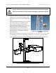
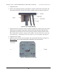
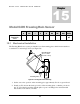
2. The mounting bracket attaches to the underside of the 6500 enclosure with 4 bolts (see
Figure 51). Position the bracket against the underside of the enclosure so that the mount-
ing holes in the bracket and enclosure align.
3. Apply RTV 162 to the threads of the four 5/16" hex mounting bolts.
4. Fasten the bracket to the enclosure with the four 5/16" hex bolts, flat washers, and lock
washers.
Figure 51. Bracket Installation