ArmorPoint I/O SELECTION GUIDE 1738 SERIES
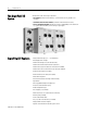
ArmorPoint I/O The ArmorPoint I/O System ArmorPoint™ I/O has three major components: y I/O modules provide the field interface, system-interface circuitry, and bases for mounting y Communication interface modules provide the network-interface circuitry y Power distribution modules provide the solution to expandability of the ArmorPoint I/O system and the flexibility to mix a variety of signal types ArmorPoint I/O Features y Highly modular design (1 pt ⎯ 8 pt modularity) y Broad application coverage y
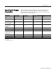
ArmorPoint I/O ArmorPoint I/O Product Compatibility PLC-5™ with Network Port SLC 500™ with Network Port PLC-5 Processor via Network Module 1756 Logix™ Communication Interface PanelView™ Terminal RSLinx™ Software 1769-L20, -L30 Controller with 1761NET Interface 1769-L35E SoftLogix5800™ PC with RSLinx Only 3 The following chart illustrates the compatibility of ArmorPoint I/O with other control platforms, especially within Rockwell Automation.
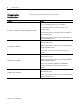
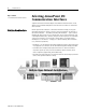
ArmorPoint I/O Communication Considerations ArmorPoint I/O features are impacted by your network choice. Network Impact The 1738-ADN12, -ADN18, and -ADN18P provide three means of connecting a node of I/O to DeviceNet. The 1738-ADNX expansion network port allows for a DeviceNet subnet. DeviceNet 1738-ADN12, -ADN18, -ADN18P, and -ADNX A total of 63 ArmorPoint I/O modules can be assembled on a single DeviceNet node. Expansion power supplies may be used to provide additional POINTBus backplane current.
ArmorPoint I/O Specifying an ArmorPoint I/O System 5 Follow these steps as you specify your ArmorPoint I/O system: 9 Step 1 Select a communication interface Choose the interface module for your operating system.
ArmorPoint I/O Step 1 - Select: y a communication interface module Selecting ArmorPoint I/O Communication Interfaces Separate communication interface adapters are available for different networks. Install adapters into the POINTBus backplane to allow ArmorPoint I/O modules to communicate with a controller. NetLinx Architecture NetLinx open network architecture is the Rockwell Automation strategy of using open networking technology for seamless, top-floor to shop-floor integration.
ArmorPoint I/O 7 Selecting a Network You can configure your system for information exchange between a range of devices and computing platforms and operating systems.
ArmorPoint I/O Selecting the DeviceNet Communication Interface ArmorPoint I/O offers four interfaces for connecting to DeviceNet. Refer to the following table.
ArmorPoint I/O 9 With the introduction of the 1738-232ASCM12 module, the amount of data to be transferred over the Subnet could become substantial. This could also occur with the 1738-ADNX and the standard DeviceNet devices connected to its Subnet connector. It is important that the total amount of data coming from the Subnet does not exceed the data capability of either the 1738-ADN12, -ADN18, -ADN18P, or -ADNX.
ArmorPoint I/O Step 2 - Select: y I/O modules - some modules have diagnostic features, electronic fusing, or individually isolated inputs/outputs Selecting ArmorPoint I/O Modules The ArmorPoint I/O family provides a wide range of input and output modules to span many applications, from high-speed discrete to process control. ArmorPoint I/O supports producer/consumer technology, which allows input information and output status to be shared among multiple Logix controllers.
ArmorPoint I/O Digital I/O Modules 11 Choose digital I/O modules when you need: y Input modules. An input module responds to an input signal in the following manner: - Input filtering limits the effect of voltage transients caused by contact bounce and/or electrical noise. If not filtered, voltage transients could produce false data. All input modules use input filtering. Optical isolation shields logic circuits from possible damage due to electrical transients. - Logic circuits process the signal.
ArmorPoint I/O Digital AC Input Modules 1738-IA2M12AC3 1738-IA2M12AC4 Number of Inputs 2 Keyswitch Position 8 Voltage, On-State Input, Nom. 120V ac Voltage, On-State Input, Min. 65V ac Voltage, On-State Input, Max. 132V ac Input Delay Time, ON to OFF, Hardware Delay, Max. 20 ms hardware filter plus 0…65 ms digital filter programmable in increments of 1 ms9 Current, On-State Input, Min. 3.7 mA Input Impedance, Nom. 10.6 kΩ Current, Off-State Input, Max. 2.
ArmorPoint I/O 13 Digital DC Output Modules 1738-OB8EM8 1738-OB8EM12 1738-OB8M23 1738-OV4EM12 1738-OB2EM12 1738-OB2EPM12 1738-OB4EM8 1738-OB4EM12 Number of Outputs 2 2 4 8 4 Keyswitch Position 1 1 1 1 1 Voltage, On-State Output, Nom. 24V dc 24V dc 24V dc 24V dc 24V dc Voltage, On-State Output, Min. 10V dc 10V dc 10V dc 10V dc 10V dc Voltage, On-State Output, Max. 28.8V dc 28.8V dc 28.8V dc 28.8V dc 28.8V dc Output Current Rating, Max. 2.0 A per module, 1.
ArmorPoint I/O Analog, Thermocouple, and RTD I/O Modules The ArmorPoint analog and temperature I/O modules support: on-board, channel-level data alarming (four set-points per channel); scaling to engineering units; channel-level diagnostics (electronic bits and LEDs); and integer format. Choose analog, thermocouple, and/or RTD I/O modules when you need: y Individually configurable channels to use the module(s) with a variety of sensors.
ArmorPoint I/O ArmorPoint I/O 15 Analog Input Modules 1738-IE2CM12 1738-IE2VM12 1738-IR2M129 1738-IT2IM129 Number of Inputs 2 2 2 2 Keyswitch Position 3 3 6 6 Input Signal Range 4…20 mA 0…20 mA 0…10V ±10V 0…600 Ω ±75 mV Input Resolution, Bits 16 bits - over 21 mA 0.32 μA/cnt 15 bits plus sign 320 μV/cnt in unipolar or bipolar mode 16 bits 9.5 mV/cnt 0.03 °C/cnt (pt 385 @ 25 °C) 15 bits plus sign 2.5 mV per count Absolute Accuracy, Current Input 0.
ArmorPoint I/O Temperature Module Alarms ArmorPoint I/O temperature modules are capable of detecting and communicating the following electronic conditions: y over-range alarm y under-range alarm y level alarm (low-low, low, high, high-high) y open-wire alarm Over-Range Alarm The channel over-range alarm is set if the input is greater than the maximum temperature (thermocouple or RTD range dependent), millivolt (+75V) or resistance (600 Ω) range value, or above the maximum range of the thermocouple or
ArmorPoint I/O 17 Cold-Junction Compensation (1738-IT2IM12 Only) When using thermocouples, cold-junction compensation is required at the termination of the thermocouple wire. Cold-junction can be accomplished in two ways: y enter an estimated temperature y an M12 terminal chamber with built-in CJC To use the M12 terminal chamber, order 871A-TS4CJC-DM (straight) or 871A-TR4CJC-DM (right-angle) Entering an estimated temperature is the least accurate way for cold-junction compensation.
ArmorPoint I/O ArmorPoint I/O Temperature Input Module Specifications 1738-IR2M12 1738-IT2IM12 Number of Inputs 2 2 Input Resolution, Bits — — Thermocouple Type and Resolution Average Over Span ⎯ Type B, 30…1820° C, 3 counts/ ° C Type C, 0…2315° C, 6 counts/ ° C Type E, -270…1000° C, 24 counts/ ° C Type J, -210…1200° C, 21 counts/ ° C Type K, -270…1372° C, 13 counts/ ° C Type N, -270…1300° C, 11 counts/ ° C Type R, -50…1768.1° C, 4 counts/ ° C Type S, -50...1768.
ArmorPoint I/O Specialty I/O Modules 19 1738-232ASCM12 and 1738-485ASCM12 The 1738-232ASCM12 and -485ASCM12 serial-interface modules offer a serial-link communication interface solution for peripheral products with: y RS-232 ports use the 1738-232ASCM12 y RS-485 and RS-422 ports use the 1738-485ASCM12 These modules allow a device with serial-interface output, i.e., bar code readers, to communicate up to 128 bytes of ASCII data onto any network supported by ArmorPoint I/O.
ArmorPoint I/O ArmorPoint I/O ASCII Module Specifications 1738-232ASCM12 1738-485ASCM12 Number of Serial Channels 1 Keyswitch Position 2 (specialty) PointBus Current (mA) 75 Power Dissipation 1.75 W @ 28.8V dc Serial Port Parameters Serial Character Framing 7N2, 7E1, 7O1, 8N1, 8N2, 8E1, 8O1, 7E2, 7O2 Serial Port Comm Speed 9600, 1200, 2400, 4800, 19.2 k, 38.
ArmorPoint I/O 21 1738-SSIM23 Module Specifications 1738-SSIM23 Number of SSI Channels 1 Keyswitch Position 2 PointBus Current (mA) 110 Power Dissipation, Max. 0.94 W Isolation Voltage Tested to 1250V ac for 60 s between each of these isolated areas: Logic side and field power Logic side and shield Shield and field power External DC Power Supply Voltage, Nom.
ArmorPoint I/O ArmorPoint I/O Counter Modules Choose the ArmorPoint I/O high-speed counters when you need: y Intelligent counter modules with their own microprocessors and I/O that are capable of reacting to high-frequency input signals up to 1 MHz. y Signals received at the inputs to be filtered, decoded, and counted. y A pulse width modulated signal. (1738-VHSC24M23 only) y Count and rate values that can be used to activate up to two embedded outputs in less than 1 ms (1738-VHSC24M23 only).
ArmorPoint I/O 23 The input voltage range is 5V dc (1738-IJM23) or 15-24V dc (1738 -VHSC24M23). The module returns the count (or frequency) in the form of a 24-bit binary number (0 to 16,777,215) expressed in a 32-bit word. Each counter has a user-selectable preset and rollover value associated with it.
ArmorPoint I/O 1738-VHSC24M23 Specifications 1738-VHSC24M23 Voltage Category/Type, Input 24V dc Current, Off-State Input, Max. ≤0.250 mA Voltage, Off-State Input, Max. ≤1.8V dc Current, On-State Input, Max. 10.2 mA @ 24V dc or 6.1 mA @ 15V dc Voltage, On-State Input, Min. ≥12.5V dc Input Filter Selections Off 10 μs (50 kHz) 100 μs (5 kHz) 1.0 ms (500 Hz) 10.0 ms (50 Hz) Input Frequency, Max. 1.
ArmorPoint I/O Step 3 - Select: 25 Selecting a Power Supply Unit y the appropriate power unit ArmorPoint I/O adapters have built-in POINTBus power supplies. All ArmorPoint I/O modules are powered from the POINTBus by either an adapter or expansion power supply. Power Specifications Cat. No. Power Supply Input Operating Voltage Voltage, Nom. Range Power Supply Inrush Current, Field Side Power Requirements, Max. Max.
ArmorPoint I/O Expansion Power Unit The 1738-EP24DC expansion power unit passes 24V dc field power to the I/O modules to the right of it. This unit extends the backplane bus power and creates a new field voltage partition segment for driving field devices for up to 17 I/O modules.
ArmorPoint I/O 27 Power Distribution General Specifications Power Supply Requirements 1738-FPD 1738-EP24DC ⎯ Note: In order to comply with CE Low Voltage Directives (LVD), you must use a Safety Extra Low Voltage (SELV) or a Protected Extra Low Voltage (PELV) power supply to power this adapter Field Side Power Requirements, Max. 24V dc (+20% = 28.8V dc max.) @ 400 mA 24V dc (+20% = 28.8V dc max.) @ 400 mA Inrush Current, Max.
ArmorPoint I/O Typical Configurations Power Distribution Options An auxiliary 24V dc power supply provides power to the POINTBus backplane and I/O modules. You can connect up to 17 I/O modules and an adapter with a maximum of 10 A field power, using the auxiliary power. The ArmorPoint field power distributor (1738-FPD) discontinues the I/O circuit power bus in order to change the field power source for I/O modules to the right of it. This allows a broad range of voltage inputs in the I/O assembly.
ArmorPoint I/O Step 4 - Select: y optional accessories, cables, and cordsets Accessories, Cables and Cordsets 29 Selecting Optional Accessories ArmorPoint Bus Extension Bases Cat. No. Description 1738-EXT1 ArmorPoint 1 meter bus extension unit 1738-EXT3 ArmorPoint 3 meter bus extension unit The following rules apply for the 1738-EXT1 and -EXT3 extension units. y Use as many as four extension units per network adapter, except the 1738-ADNX adapter.
ArmorPoint I/O Cables and Cordsets For additional information on selecting cables and cordsets for ArmorPoint I/O see: y On-Machine Connectivity Catalog, publication M115-CA001 y On-Machine Solutions Selection Guide, publication ONMACH-SG001 ArmorPoint Digital Input Module Cables Cat. No.
ArmorPoint I/O 31 ArmorPoint Analog Module Cables Cat. No. Recommended Patchcord (doubleended) Recommended Male Cordset (singleended) 1738-IE2CM12 ⎯ ⎯ 1738-IE2VM12 ⎯ ⎯ 1738-OE2CM12 ⎯ ⎯ 1738-OE2VM12 ⎯ ⎯ ArmorPoint AC and Relay Module Cables Cat. No.
ArmorPoint I/O ArmorPoint Thermocouple Terminal Chambers Cat. No. Straight Right Angle 1738-IT2IM12 871A-TS4CJC-DM 871A-TR4CJC-DM ArmorPoint DeviceNet and Auxiliary Power Cables Cat. No.
ArmorPoint I/O 33 Step 5 - Select: Determining Mounting Requirements Placing ArmorPoint I/O Modules The producer/consumer model multicasts messages. This means that multiple nodes can consume the same data at the same time from a single device. Where you place I/O modules in the control system determines how the modules exchange data.
ArmorPoint I/O Power Supply Distance Rating Modules are placed to the right of the power supply. Each ArmorPoint I/O module can be placed in any of the slots to the right of the power supply until the usable backplane current of that supply has been exhausted. An adapter provides 1 A current to the POINTBus. The 1738-EP24DC provides up to 1.3 A and I/O modules require from 75 mA (typical for the digital and analog I/O modules) up to 220 mA or more. POINTBus Current Requirements Cat. No.
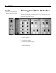
ArmorPoint I/O Mounting the ArmorPoint I/O System 35 You can panel mount the ArmorPoint I/O system in the horizontal or vertical orientation.
ArmorPoint I/O Related Documentation Additional user documentation presents information according to the tasks you perform and the programming environment you use. Refer to the table below for information on 1738 ArmorPoint I/O products. ArmorPoint I/O Related Publications9 Cat. No. General Information Pinout Wiring Diagrams ⎯ DC Pub.No.
ArmorPoint I/O ArmorPoint I/O 37 ArmorPoint I/O Related Publications9 Analog Serial Interface Modules Counters Power Units Cat. No. Description 1738-IE2CM12 24V dc Analog Current Input w/ 2 M12 connectors 1738-IE2VM12 24V dc 2 Analog Voltage Input w/ 2 M12 connectors 1738-OE2CM12 24V dc Analog Current Output w/ 2 M12 connectors 1738-OE2VM12 24V dc Analog Voltage Output w/ 2 M12 connectors Pub.No.
ArmorPoint I/O Publication 1738-SG001B-EN-P
ArmorPoint I/O 39 Publication 1738-SG001B-EN-P
The following are trademarks of Rockwell Automation: ArmorPoint, POINTBus, PLC-5, SLC 500, Logix, NetLinx, PanelView, RSLinx, RSNetWorx, and SoftLogix. Trademarks not belonging to Rockwell Automation are property of their respective companies. Part Number 957974-13 Publication 1738-SG001B-EN-P – July 2005 Supersedes 1738-SG001A-EN-P – October 2004 Copyright ©2005 Rockwell Automation, Inc. All Rights Reserved. Printed in USA.