
User manual

1 Publication CIG-WD001B-EN-P - May 2005
Chapter
5
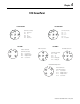
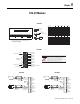
1746 I/O Modules
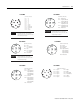
Desc riptio n Axis 1 Axis 2 Axis 3 Axis 4 System
Re serve d
4, 3, 2, 1
Digit al O UT-
Dig ital OUT+ (+24EXT )
18 14 10
6
Digit al I N-
19 15 11 7
Digit al I N+
20 16 12 8
-24V dc RET
21
+24V dc EXT
22
Analog OUT- (GND)
Analog OUT+
Analog IN-
Analog IN+
Excitation- (-10V) 39
Excitation+ (+1 0V)
40
17
13
95
23 27 31 35
24 28 32 36
25 29 33 37
26 30 34 38
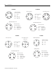
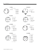
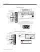
We recommend making connections to the 1746-BLM module with:
-- Interface module (1492-IFM40F)
-- Interface cable (1492-CABLE010H)
22
21
16
15
14
13
+
-
+
-
+
-
+ 24V EXT
dc common
digital output
sync output
digital input
start-of-drop trigger
24V dc
supply
1
2
39
40
: : : : : : : : : : : : : : : : : : : :
1
39
2
40
1492-IFM40F
1746-BLM
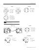
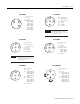
CJC A+
CJC A-
Do NOT use these
connections
CJC B+
CJC Assembly
CJC Assembly
CJC B-
Retaining Screw
Retaining Screw
Channel 0+
Channel 0-
Channel 1+
Channel 1-
Channel 2+
Channel 2-
Channel 3+
Channel 3-
n/c
spare part catalog number:
1746-RT32
Do not remove or loosen the cold junction compensating
thermistors located on the terminal block. Both thermistors
are critical to ensure accurate thermocouple input
readings at each channel. The module will not operate in the
thermocouple mode if a thermistor is removed
ATTENTION
1746-BTM
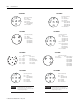
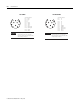
0
1
2
9
10
11
3
4
5
6
7
8
+
-
analog
source
earth
ground
Jumper
unused
inputs.
LOAD
earth
ground
Do not jumper
unused outputs.
IN 0+
IN 0-
ANL COM
IN 1+
IN 1-
ANL COM
not used
OUT 0
ANL COM
not used
OUT 1
ANL COM
0
1
2
9
10
11
3
4
5
6
7
8
+
-
analog
source
earth
ground
Jumper
unused
inputs.
LOAD
earth
ground
Do not jumper
unused outputs.
IN 0+
IN 0-
ANL COM
IN 1+
IN 1-
ANL COM
not used
OUT 0
ANL COM
not used
OUT 1
ANL COM
1746-FIO4I 1746-FIO4V