
User manual

1 Publication CIG-WD001B-EN-P - May 2005
Preface
Introduction
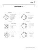
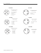
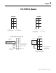
The purpose for showing these connection diagrams here is to
illustrate the following attributes of each I/O module, I/O block, or
fixed I/O controller:
• the number of inputs and/or outputs
• whether there is a single common for all I/O, a common for a
set of I/O separate from other sets of I/O, or a signal return for
each I/O circuit so that each I/O circuit is isolated from all
others
• whether an output is a current source or a current sink
• whether an input is a source load or a sink load
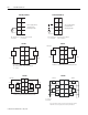
To fit them into this concise format, these diagrams are intentionally
simplified to the point that they do not show the type of cables,
twisted pairs, cable shields or the grounding of cable shields. We
make an exception where the cable shield must be connected at an
I/O terminal.
For those input modules or blocks that can tolerate the leakage
current of proximity sensors, we usually show a proximity sensor at
one input and hard contacts at the others for ease of illustration.
IMPORTANT
Many of the catalog numbers included in this
publication have specific wiring guidelines and
recommendations that are listed in the product’s
technical documentation (e.g. installation instructions
or user manuals) but not here because the purpose
of this publication is to show connection diagrams
and basic information required to wire each I/O
module.
For a full description of how to use each of the
catalog numbers listed in this publication, see the
individual product’s technical documentation.