
User manual

Publication CIG-WD001B-EN-P - May 2005
1756 ControlLogix I/O Modules 7-3
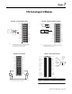
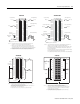
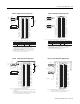
From 1756-HYD02
HOME
IN_COM
+–
24V dc
Field Power
Supply
General cable
C0720
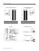
From 1756-HYD02
+OK
-OK
24V dc
Field Power
Supply
+–
OK Pilot
Relay
OK Pilot
Relay
Contacts
Start
Stop
CR1
CR1
CR1
M1
24V AC/DC
or 120VAC
typical
General cable
C0720
1756-HYD02 - Wiring Home Limit Switch 1756-HYD02 - Wiring OK Contacts
12
34
5
6
7
8
910
11
12
1314
1516
1718
19
20
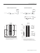
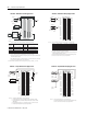
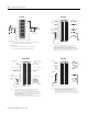
1. All terminals with the same name are connected together on the module. For
example, L2 can be connected to any terminal marked L2-0.
2. When you daisy chain from a group to another RTB, always connect the daisy
chain as shown above. Do not connect more than 2 wires to any single terminal.
3. This wiring example shows a single voltage source.
L2
L1
Daisy
chain to
other
RTBs
Group 0
Group 0
Group 1Group 1
IN-1
IN-3
IN-5
IN-7
L2-0
IN-9
IN-11
IN-13
IN-15
L2-1
IN-0
IN-2
IN-4
IN-6
L2-0
IN-8
IN-10
IN-12
IN-14
L2-1
NOTES:
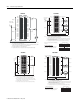
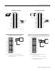
Non-isolated
wiring
Isolated
wiring
12
34
56
78
910
1112
1314
1516
1718
1920
2122
2324
2526
2728
2930
3132
3334
3536
Daisy chain t
L2-0
L2-0
L2-1
L2-2
L2-3
L2-8
L2-4
L2-5
L2-6
L2-7
Not used
L2-9
L2-10
L2-11
L2-12
L2-13
L2-14
L2-15
L2-15
IN-0
IN-1
IN-2
IN-3
IN-8
IN-4
IN-5
IN-6
IN-7
Not used
IN-9
IN-10
IN-11
IN-12
IN-13
IN-14
IN-15
Not used
L2-2
L2-4
L2
L1
L1-0
L1-2
L1-4
o other RTBs
1. All terminals with the same name are connected together on the module. For
example, L2 can be connected to either terminal marked L2-15.
2. When you use the second L2-15 terminal to daisy chain to other RTBs, always
connect the daisy chain to the terminal directly connected to the supply wire, as
shown in the example above.
NOTES
Do not connect more than 2 wires to any single terminal.
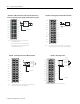
Jumper bar - Cut to length
(Part number 97739201)
1756-IA16 1756-IA16I