
User manual

Publication 1734-UM015A-EN-E - November 2009
DeviceLogix Capabilities 75
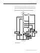
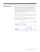
This flowchart shows the process and priority the module follows when
updating each Digital Output Point (DOP). The process considers module
states such as Network Fault and Run/Idle, configurable parameters such as
Network Fault Override, and Logic states such as Logic Enabled and Force.
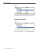
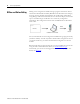
Output Ownership (Value Source Selector Behavior for Bound Outputs)
Update
Output
End
Network
Fault
Logic
Enabled
Perform Logic
Program
Apply Force Value
Apply Value to DOP
Network
Fault
Override
Yes
Yes
Yes
Fault Exists
Receive Idle
DOP in RUN mode
Disabled
Explicit Message Request
to change DOP value
I/O Message to
change DOP value
DOP in
Available State
Return Object State
Conflict Error
Use Idle Action
and Idle Value
Ignore Message
EM
Comm
Override
I/O
Fault
Idle
Run
Available
Use Fault Action
and Fault Value
Clear DOP Value
DOP: Digital Output Point
EM: Explicit Message