
User manual

91 Publication 1734-UM015A-EN-E - November 2009
Appendix
A
Peer Data Maps
About This Appendix
This appendix contains information to help you use peer data from
POINT I/O and ArmorPOINT I/O modules in your DeviceLogix program.
For descriptions or details on the individual modules, refer to the Installation
Instructions or User Manual for the specific modules.
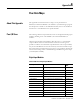
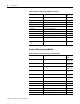
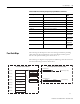
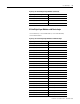
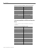
Peer I/O Sizes
The following tables list the produced I/O sizes of the digital and analog input
modules, including those of the POINT I/O and ArmorPOINT I/O
modules.
Only the input modules are listed below. The data sent to or consumed by
output modules cannot be used in Peer data connections. Although it is
possible to read the status information produced from some output modules,
they are not included here for the sake of brevity. If another module’s output
data is required in your DeviceLogix program, it is suggested that this data be
sent from the owning master to the DeviceLogix module through the output
(consumed) data assembly.
Digital Input Modules
Produced I/O Sizes of Digital Input Modules
Catalog Number Description Produced
Size
1734-IB2 2-point sinking DC input 1
1738-IB2M12 (M8) 2-point sinking DC input 1
1734-IB4 4-point sinking DC input 1
1738-IB4M12 (M8) 4-point sinking DC input 1
1734-IB4D 4-point sinking DC input with diagnostics 2 (default), 1
1738-IB4DM12 4-point sinking DC input with diagnostics 2 (default), 1
1734-IB8 8-point sinking DC input 1
1738-IB8M12 (M8, M23) 8-point sinking DC input 1
1734-IV2 2-point sourcing DC input 1
1734-IV4 4-point sourcing DC input 1
1738-IV4M12 (M8) 4-point sourcing DC input 1
1734-IV8 8-point sourcing DC input 1
1738-IV8M12 (M8, M23) 8-point sourcing DC input 1